Low power phototransistor-based welding helmet providing reduced sensitivity to low intensity light and sharp phototransistor response to high intensity light
What is Al technical title?
Al technical title is built by PatSnap Al team. It summarizes the technical point description of the patent document.
a low-power, welding helmet technology, applied in the direction of optical radiation measurement, instruments, spectrophotometry/monochromators, etc., can solve the problems of excessive power consumption, heavy loads still needed, metal can phototransistors are relatively big and bulky, etc., to prolong the battery life of the invention's power supply, improve the efficiency of circuit design, and save energy
Inactive Publication Date: 2005-02-15
KIMBERLY-CLARK WORLDWIDE INC
View PDF7 Cites 6 Cited by
Summary
Abstract
Description
Claims
Application Information
AI Technical Summary
This helps you quickly interpret patents by identifying the three key elements:
Problems solved by technology
Method used
Benefits of technology
One feature of the present invention is the use of a resistor coupled between the base and emitter of the phototransistor. This resistor helps reduce the current produced by the sensor during low ambient light conditions, thereby attenuating the phototransistor output in response to low intensity light signals, and helps produce a sharply rising voltage from the phototransistor in response to high intensity light signals. Preferably, the feedback circuit also includes a second resistor coupled between the emitter of a feedback transistor and ground to further attenuate phototransistor output in the presence of low intensity ambient light.
Yet another feature of the present invention is its use of a selector circuit for selecting the drive signal that will be delivered to the shutter assembly. If the sensor circuit indicates to the selector circuit that a welding arc is present, the selector circuit will cause a dark state drive signal to be delivered to the shutter assembly. If the sensor circuit indicates to the selector circuit that no welding arc is present, the selector circuit will cause a “clear state” drive signal to be delivered to the shutter assembly. The selector circuit uses a transistor as a switch to control the selection of the drive signal. An RC circuit is part of the selector circuit. The RC circuit utilizes its RC time constant to delay the transition of the “dark state” drive signal to the “clear state” drive signal, thus preventing the shutter assembly from switching to a clear state during brief “off” periods in the weld pulsations that exist with various weld types.
Problems solved by technology
To prevent the photodiode from saturating, a steadily increasing load must be put on the photodiode which leads to excessive power consumption.
While the circuits disclosed in these patents utilize feedback to bias the phototransistor and avoid the excessive drawing of current, heavy loads were still needed.
Metal can phototransistors are relatively big and bulky.
Their size, height and relative difficulty in mounting serves as a limiting factor in the ability of designers to reduce the size of the units in which the sensor circuit is implemented.
This additional circuitry not only complicated circuit design, but also increased the drain on the power supply.
Method used
Image
Click on the blue label to locate the original text in one second.
Reading with bidirectional positioning of images and text.
Examples
Embodiment Construction
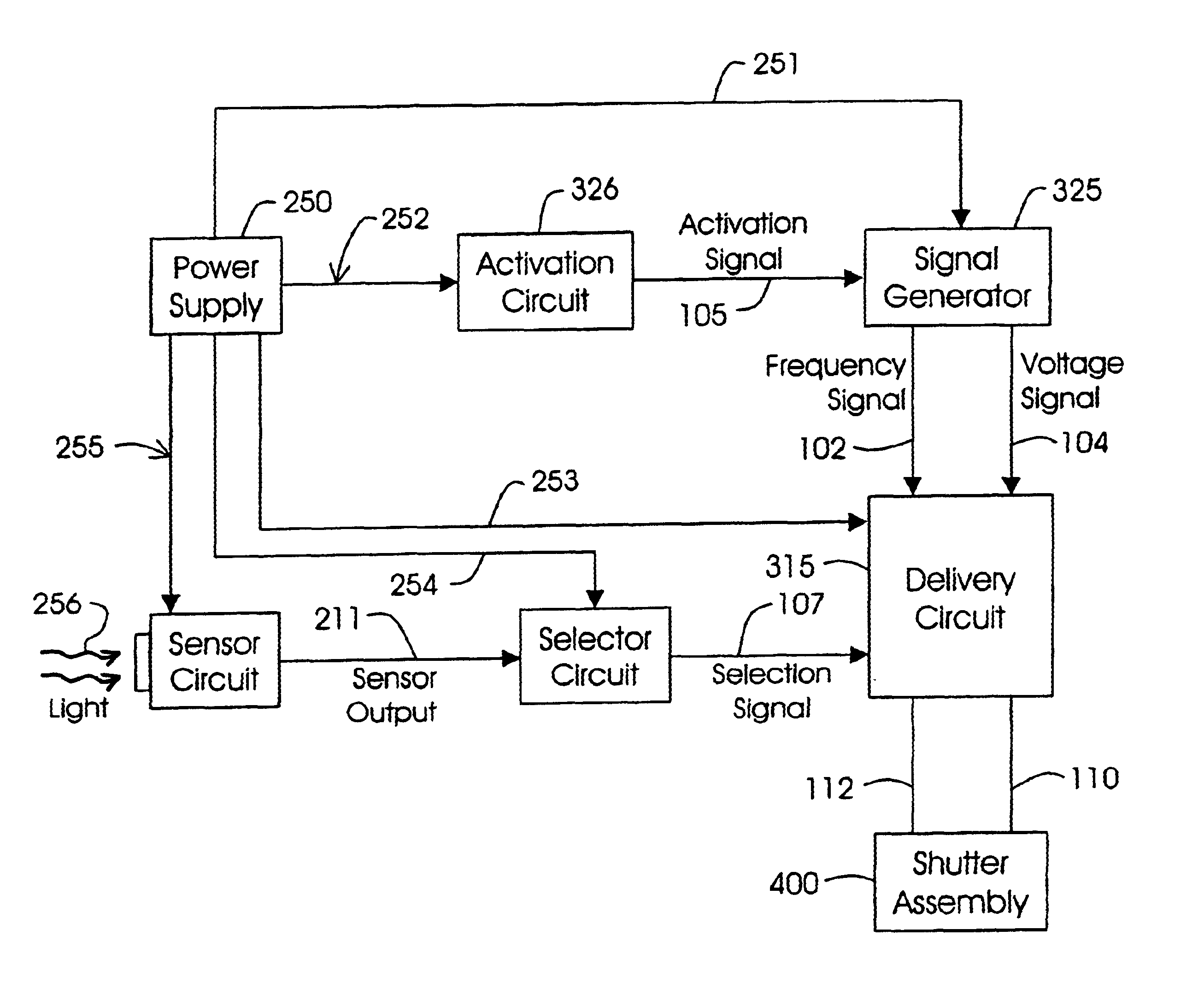
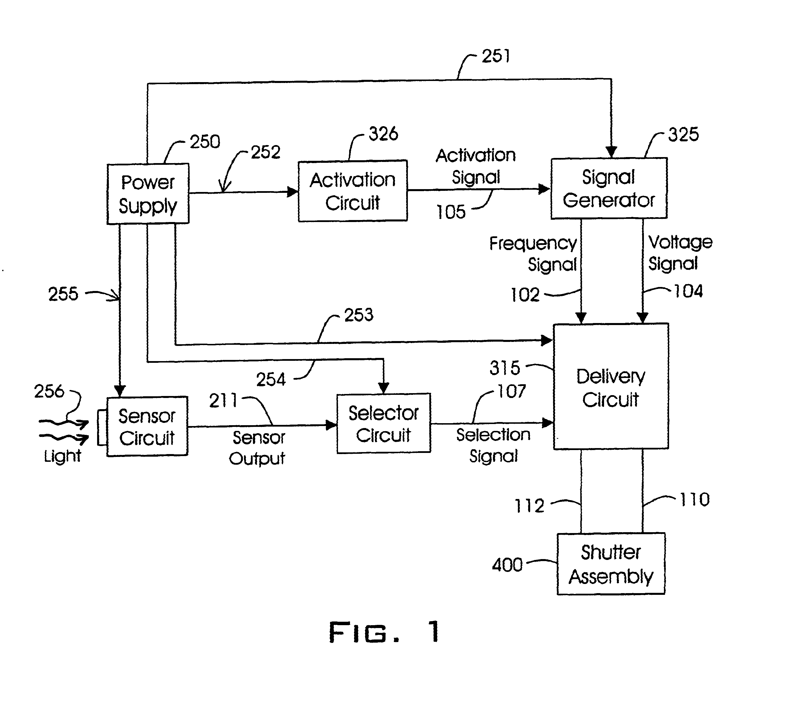
A block diagram of the circuit of the present invention is depicted in FIG. 1. As can be seen, a power supply 250 is connected via power lines 251, 252, 253, 254, and 255 to the sensor circuit 200, activation circuit 326, selector circuit 316, signal generator 325, and delivery circuit 315. The power supply 250 furnishes the circuit with the power necessary for operation. Activation circuit 326, selector circuit 316, signal generator 325, and delivery circuit 315 function together to control the shutter assembly 400 depending upon the signals received from power supply 250 and sensor circuit 200.
Activation circuit 326 receives power from the power supply 250 and sends an activation signal to the signal generator 325. Upon activation by the activation circuit, the signal generator 325 generates a frequency signal 102 and a voltage signal 104 and sends the two signals 102 and 104 to the delivery circuit 315. The delivery circuit 315 uses the frequency signal 102 and the voltage signal...
PUM
Abstract
A sensor circuit for detecting the occurrence of welding is disclosed. The sensor circuit uses a phototransistor operative to receive a light input and produce an output representative thereof. A resistor is coupled between the phototransistor's base and emitter to control the phototransistor's response to low intensity and high intensity light. An amplifier may be coupled to the output of the phototransistor so as to provide a gain for the output of the phototransistor; and feedback means may coupled to the phototransistor to bias the phototransistor, the feedback means comprising a resistor capacitor circuit for following the output of the phototransistor, a feedback transistor to provide a feedback signal to the phototransistor, and a resistor coupled between the base and the emitter of the phototransistor. Preferably the phototransistor is a planar phototransistor having a surface mount. The sensor circuit may also be used in an auto-darkening eye protection device, such as a welding helmet or the like, that delivers a drive signal to a shutter assembly upon the detection of welding, the drive signal being operative to drive the shutter assembly to a darkened, protective state. A solar cell may be used to reduce the circuit's power consumption by powering various circuit components only when the welding helmet is exposed to light. The present invention provides reduced power consumption, improved attenuation of low intensity light signals, a sharp rise time from the phototransistor in response to high intensity light, and allows implementation into a smaller sleeker eye protection device.
Description
BACKGROUND OF THE INVENTIONThe present invention relates to the field of auto-darkening eye protection devices, such as welding helmets having a shutter (or lens) assembly that automatically darkens upon the detection of a welding arc. A photosensitive device such as a photodiode or a phototransistor may be used to sense the intensity of light incident on the area of the shutter assembly so as to provide an indication to the circuitry controlling the shutter assembly that the shutter assembly needs to be driven to either a dark state or a clear state. If a welding arc is present, the welding helmet protects the eyes of the welder from any danger caused by the intensity of the welding arc by driving the shutter assembly to a dark state, thereby decreasing the amount of energy passing through the lens to the welder's eyes. U.S. Pat. Nos. 4,385,806, 4,436,376, 4,540,243, Re. 32,521, U.S. Pat. Nos. 5,248,880, 5,252,817, 5,347,383, 5,533,206, 5,751,258, 5,959,705, 6,067,129, and 6,070,26...
Claims
Application Information
Patent Timeline
Application Date:The date an application was filed.
Publication Date:The date a patent or application was officially published.
First Publication Date:The earliest publication date of a patent with the same application number.
Issue Date:Publication date of the patent grant document.
PCT Entry Date:The Entry date of PCT National Phase.
Estimated Expiry Date:The statutory expiry date of a patent right according to the Patent Law, and it is the longest term of protection that the patent right can achieve without the termination of the patent right due to other reasons(Term extension factor has been taken into account ).
Invalid Date:Actual expiry date is based on effective date or publication date of legal transaction data of invalid patent.