Light source apparatus, optical amplifier and optical communication system

a technology of light source apparatus and optical amplifier, which is applied in the direction of optical elements, semiconductor lasers, instruments, etc., can solve the problems of low yield of light emitting elements which can be used for wavelength division multiplexing, high cost, and difficult maintenance of optical repeaters

Inactive Publication Date: 2005-02-15
FUJITSU LTD
View PDF24 Cites 1 Cited by
  • Summary
  • Abstract
  • Description
  • Claims
  • Application Information

AI Technical Summary

Benefits of technology

Accordingly, it is an object of the present invention to provide a light source apparatus which can produce a beam of light having a desired center wavelength irrespective of a spectrum of a light emitting element.

Problems solved by technology

On the other hand, where an optical fiber transmission line is laid on the bottom of the sea, since an optical repeater having the EDFA must be kept sunk on the bottom of the sea, maintenance of the optical repeater is very difficult.
However, the spectrum of a light emitting element is liable to be dispersed due to an error in production or the like, and there is a problem that the yield of light emitting elements which can be used for wavelength division multiplexing is low.
While a variable wavelength light source is known as one of light source apparatus of the type mentioned, the variable wavelength light source has a problem in that it is expensive.

Method used


Image

  • Light source apparatus, optical amplifier and optical communication system
  • Light source apparatus, optical amplifier and optical communication system
  • Light source apparatus, optical amplifier and optical communication system

Examples


first embodiment

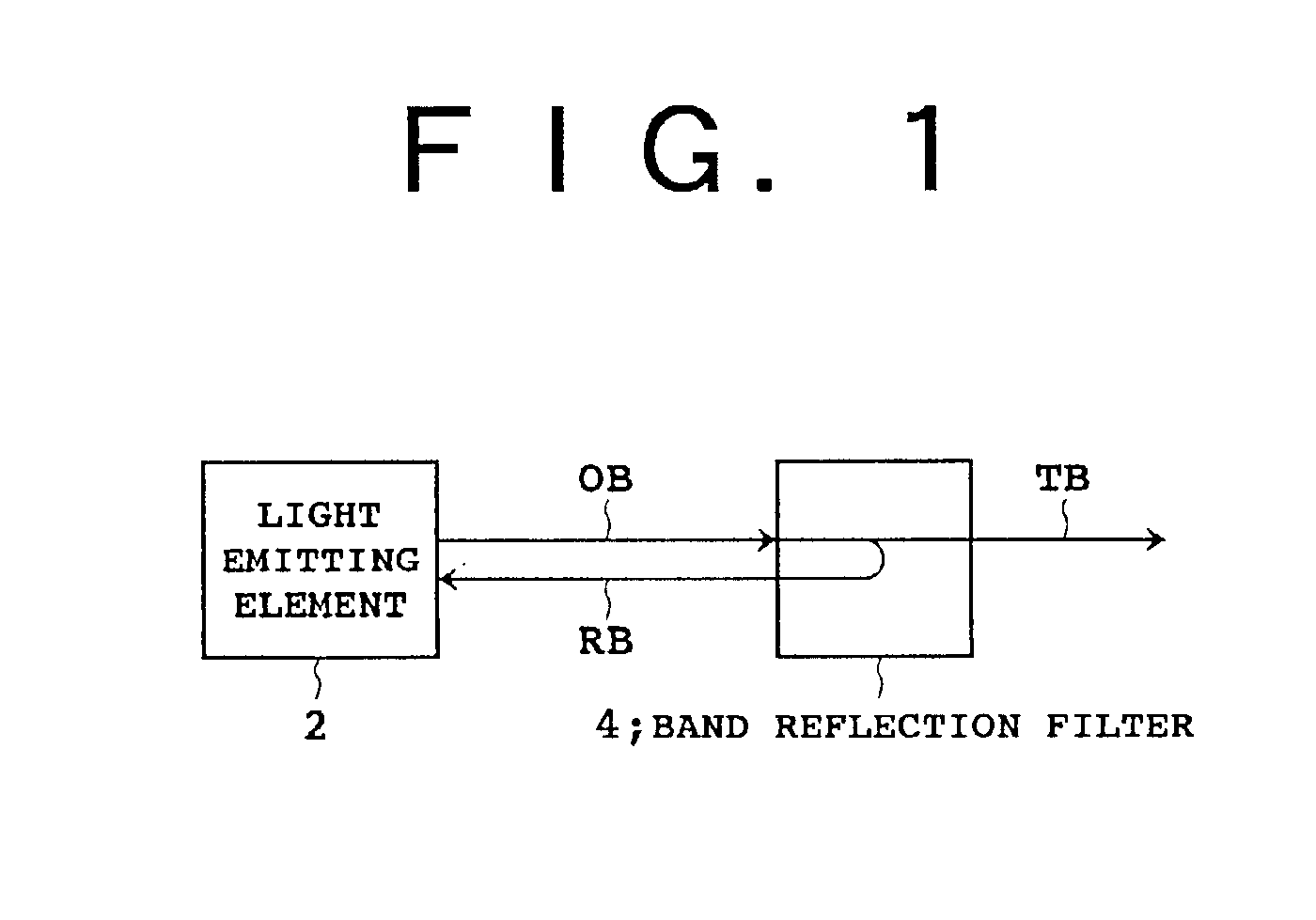
FIG. 5 is a diagrammatic view showing the light source apparatus according to the present invention. A light emitting element 2 and an optical fiber 6 are optically connected to each other by a lens 8. A fiber grating FG as the band-reflection filter 4 is formed intermediately or at an end of the optical fiber 6. A light beam OB outputted from the light emitting element 2 is converged by the lens 8 and introduced into a core 6a of the optical fiber 6 through an end surface of the same. Part of the light beam OB supplied to the optical fiber 6 is Bragg reflected by the fiber grating FG and outputted as a reflection beam RB from the end surface of the core 6a. The reflection beam RB outputted from the optical fiber 6 is converged by the lens 8 and introduced into the light emitting element 2. A transmission beam TB which has passed through the fiber grating FG is used as an optical output of the light source apparatus to various applications.

In the present embodiment, since the fiber ...

second embodiment

Referring to FIG. 6, there is shown the light source apparatus of the present invention. In order to optically connect a light emitting element 2 and an optical fiber 10 to each other by means of a collimate beam system, lenses 12 and 14 are interposed in this order between the light emitting element 2 and the optical fiber 10. Here, the band reflection filter 4 is a dielectric multi-layer film filter 16 interposed between the lenses 12 and 14. The filter 16 includes a transparent substrate 18 made of glass or the like, and a dielectric multi-layer film 20 formed on the transparent substrate 18. The dielectric multi-layer film 20 is obtained, for example, by forming SiO2 layers of a low refractive index and TiO2 layers of a high refractive index layered alternately so that it has totaling several to several tens layers. The dielectric multi-layer film 20 is disposed perpendicularly to a collimate beam between the lenses 12 and 14 in order to secure a necessary coupling efficiency of...

third embodiment

FIG. 7 is a schematic view showing the light source apparatus according to the present invention. Here, an etalon plate 22 substituted for the dielectric multi-layer film filter 16 of FIG. 6 is used as the band-reflection filter 4. The material of the etalon plate 22 is, for example, quartz, and the etalon plate 22 has two surfaces parallel to each other. Each of the two surfaces is set perpendicularly to a collimate beam between the lenses 12 and 14 in order to secure a necessary coupling efficiency of the reflection beam RB to the light emitting element 2.

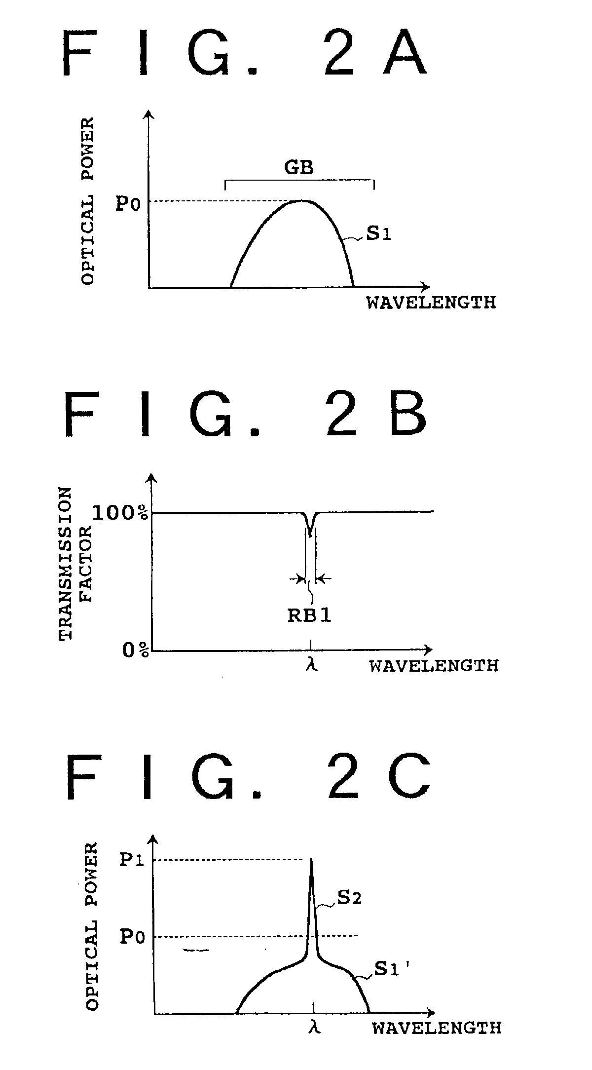
Where the etalon plate 22 is used as the band reflection filter 4, the center wavelength λ of the reflection band RB1 illustrated in FIG. 2B can be adjusted by the thickness of the etalon plate 22, and the values of the finesse, which represents the sharpness of the drop of the transmission factor in the proximity of the wavelength λ, and the lowest transmission factor can be adjusted by the reflection factors of the two surfaces...


PUM


Abstract

An apparatus has first and second light sources, a plurality of filters, and an optical switch. The light sources output a light beam having a spectrum determined by a gain band thereof. The plurality of filters each have a reflection band included in the gain band. The optical switch selectively couples the filters to the light source. The first and second light sources provide pumping light to a single transmission line. The first and second filters are configured so as to not reflect signal light to be amplified.

Description

BACKGROUND OF THE INVENTION1. Field of the InventionThis invention relates generally to application of light emitting elements such as light emitting diodes and laser diodes to evaluation of optical devices, amplification of optical signals, and optical communication, and more specifically to a light source apparatus suitable for production of pump light for an optical amplifier or for evaluation of a passive optical device as well as an optical amplifier and an optical communication system which includes a light source apparatus of the type just mentioned.2. Description of the Related ArtAs a result of establishment of a technology for production of silica fibers of a low loss (for example, 0.2 dB / km), an optical communication system which includes an optical fiber as a transmission line has been put into practical use. The optical communication system includes a first terminal station having an optical transmitter which outputs an optical signal, an optical fiber transmission line...

Claims


Application Information

Patent Timeline
Patent Type & Authority Patents(United States)
IPC IPC(8): H01S3/06H01S3/067H01S3/0915H01S3/094H01S3/0933H01S3/10H01S5/00H04B10/2537H04B10/294H04B10/40H04B10/50H04B10/60
CPCH01S3/06754H01S3/094096H01S3/094011H01S3/0933
Inventor NAGANUMA, NORIHISASHUKUNAMI, NORIFUMI
Owner FUJITSU LTD
Why Eureka
Try Eureka