Apparatus for the electrostatic cleaning of gases and method for the operation thereof

a technology of electrostatic cleaning and apparatus, which is applied in the direction of electrode cleaning, colloidal chemistry, separation processes, etc., can solve the urgent practical problem of filtering gases containing mainly submicron particles, consume a relatively large amount of energy, and the effectiveness of presently available gas purification equipment is not satisfactory, so as to achieve the effect of improving efficiency

Inactive Publication Date: 2005-02-22
KERNFORSCHUNGSZENTRUM KARLSRUHE GMBH
View PDF14 Cites 48 Cited by
  • Summary
  • Abstract
  • Description
  • Claims
  • Application Information

AI Technical Summary

Benefits of technology

to provide a gas purification apparatus wherein gases can be purified with improved efficiency.

Problems solved by technology

The filtering of gases containing mainly submicron-particles is an urgent practical problem.
The effectiveness of presently available gas purification equipment is not satisfactory.
This however consumes a relatively large amount of energy.
Again, this increases the energy consumption for the electrostatic charging of the particle and also the size of the gas purification plant.
The effectiveness of most of these devices however is limited by the low velocity of the gas flow.
In many devices, the collection of submicron particles also causes a high-pressure loss, which results in high-energy consumption.
The known technical solutions have several disadvantages: For the electrical charging of the particles, long arrangements of electrodes are needed for a corona discharge in the space between the electrodes.
This does not provide for an effective electric charging of the particles in the gas at all locations in the space between the electrodes.
However, this requires several ionization devices, which renders the gas purification plant relatively complex.
The high voltage ionization devices require large amounts of compressed air and therefore increase the energy consumption.
Filters or absorbers washed by water require large amounts of water for spraying and increase the pressure losses in the gas purification plant.

Method used


Image

  • Apparatus for the electrostatic cleaning of gases and method for the operation thereof
  • Apparatus for the electrostatic cleaning of gases and method for the operation thereof
  • Apparatus for the electrostatic cleaning of gases and method for the operation thereof

Examples


Embodiment Construction

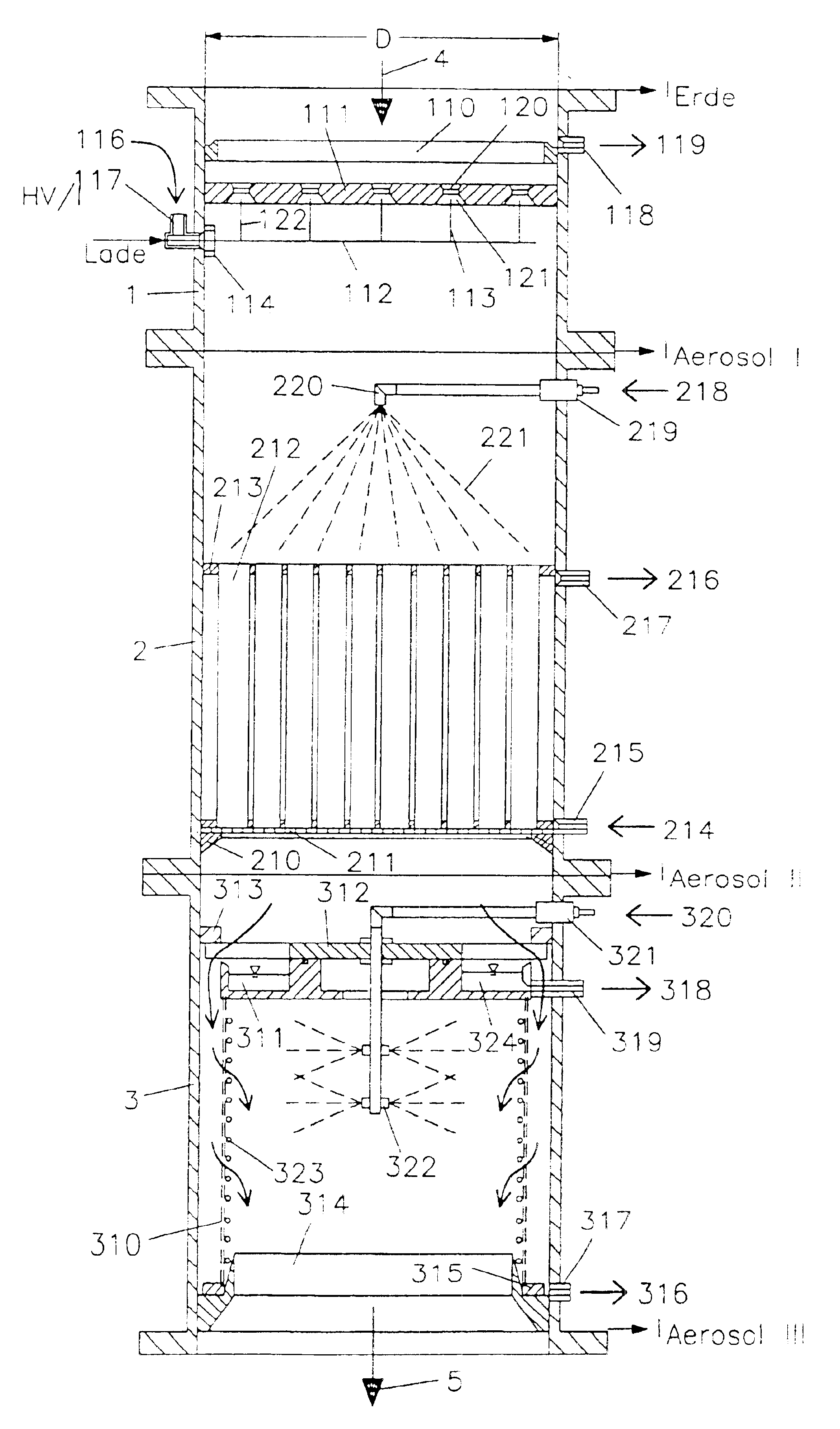
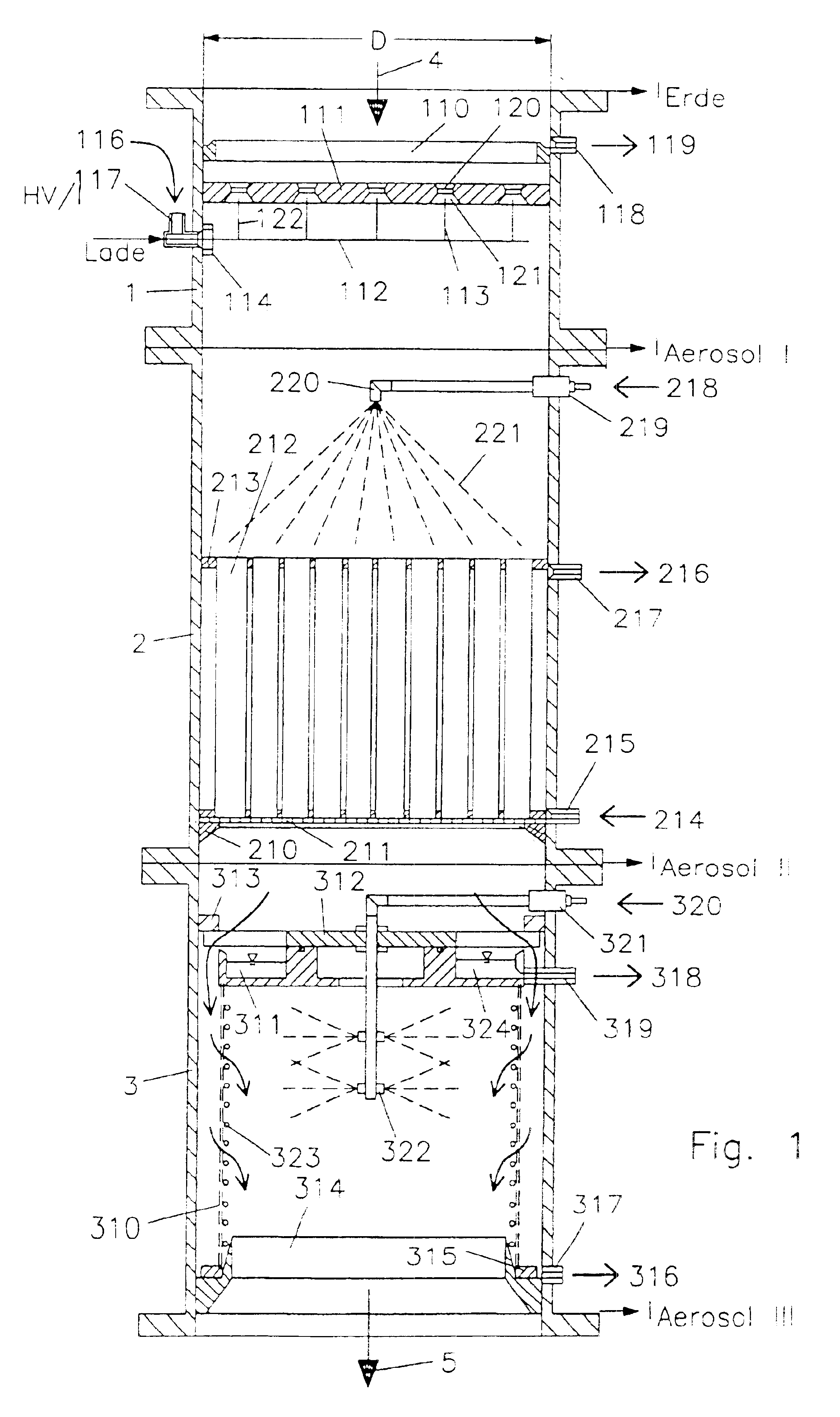
The front side of the tube bundle 212 facing the gas stream is disposed at a distance from the high voltage electrode 112 of the charging unit, which is 1.5 to 5 times the diameter D of the grounded electrode plate. D, that is the inner diameter of the gas conduit section 1 or, respectively, 2 or, respectively, 3 of the gas conduit including the gas to be cleaned, has a size in a range such that, with the raw gas volume flow divided by the area corresponding to D, a gas flow speed of 0.1 to 10 m / sec, preferably 0.5 to 2 m / sec, is obtained. This is known from the gas flow dynamics. The dimension are therefore determined in accordance with the gas volume and the flow speed. The length of the grounded electrodes 212, that is of the tubes 212, can be deduced from the main parameter D as follows:

0.5D<L<5D.

The apparatus for the electrostatic cleaning of gas comprises in accordance with the schematic representation of FIG. 1, the first conduit section 1 including the electrostati...


PUM

PropertyMeasurementUnit
mass concentrationaaaaaaaaaa
heightaaaaaaaaaa
volumeaaaaaaaaaa

Abstract

In an apparatus for the purification of a gas which apparatus includes a three section conduit with
    • an ionization and cleaning section in which particles contained in water-saturated air are ionized and then conducted through a chamber with grounded walls so that part of the particles are deposited on these walls,
    • an additional cleaning section which includes grounded tubes past which the gas is conducted to remove additional charged particles and
    • a filter section in which dry remaining fine particles are removed from the gas stream,
    • the deposited particles are flushed from all three sections and the flushing water including the particles is cleaned and recycled.

Description

BACKGROUND OF THE INVENTIONThe invention resides in a method and an apparatus for cleaning industrial gases by the removal of solid and liquid particles as they or contained for example in the gases generated by municipal waste combustion in the metallurgical, chemical and other industrial plants.The filtering of gases containing mainly submicron-particles is an urgent practical problem. The effectiveness of presently available gas purification equipment is not satisfactory.If possible at all, purification of gases including submicron particles requires high gas speeds. Often cyclones are used herefor, wherein the gas flow is rotated utilizing the centrifugal forces for the particle separation. This however consumes a relatively large amount of energy. In electrostatic separators, on the other hand, the number of electric fields or the length of the high voltage electrodes or of the grounded electrodes must be increased. Again, this increases the energy consumption for the electrost...

Claims


Application Information

Patent Timeline
Patent Type & Authority Patents(United States)
IPC IPC(8): B03C3/02B03C3/49B03C3/53B03C3/45B03C3/16B01D46/24B03C3/40B03C3/155B03C3/78B03C3/82
CPCB03C3/16B03C3/49B03C3/53Y10S55/38B03C2201/06
Inventor BOLOGA, ANDREIWASCHER, THOMASPAUR, HANS-RUDOLFBAUMANN, WERNER
Owner KERNFORSCHUNGSZENTRUM KARLSRUHE GMBH
Why Eureka
Try Eureka