Eureka AIR delivers breakthrough ideas for toughest innovation challenges, trusted by R&D personnel around the world.

Multi-axis numerical control electromachining of bladed disks

a numerical control and electromachining technology, applied in the field of electromachining, can solve the problems of large number of pits or craters, high equipment cost, and long cycle time of milling process, and achieve the effect of high metal erosion

Inactive Publication Date: 2005-02-22
GENERAL ELECTRIC CO
View PDF7 Cites 26 Cited by
  • Summary
  • Abstract
  • Description
  • Claims
  • Application Information

AI Technical Summary

Benefits of technology

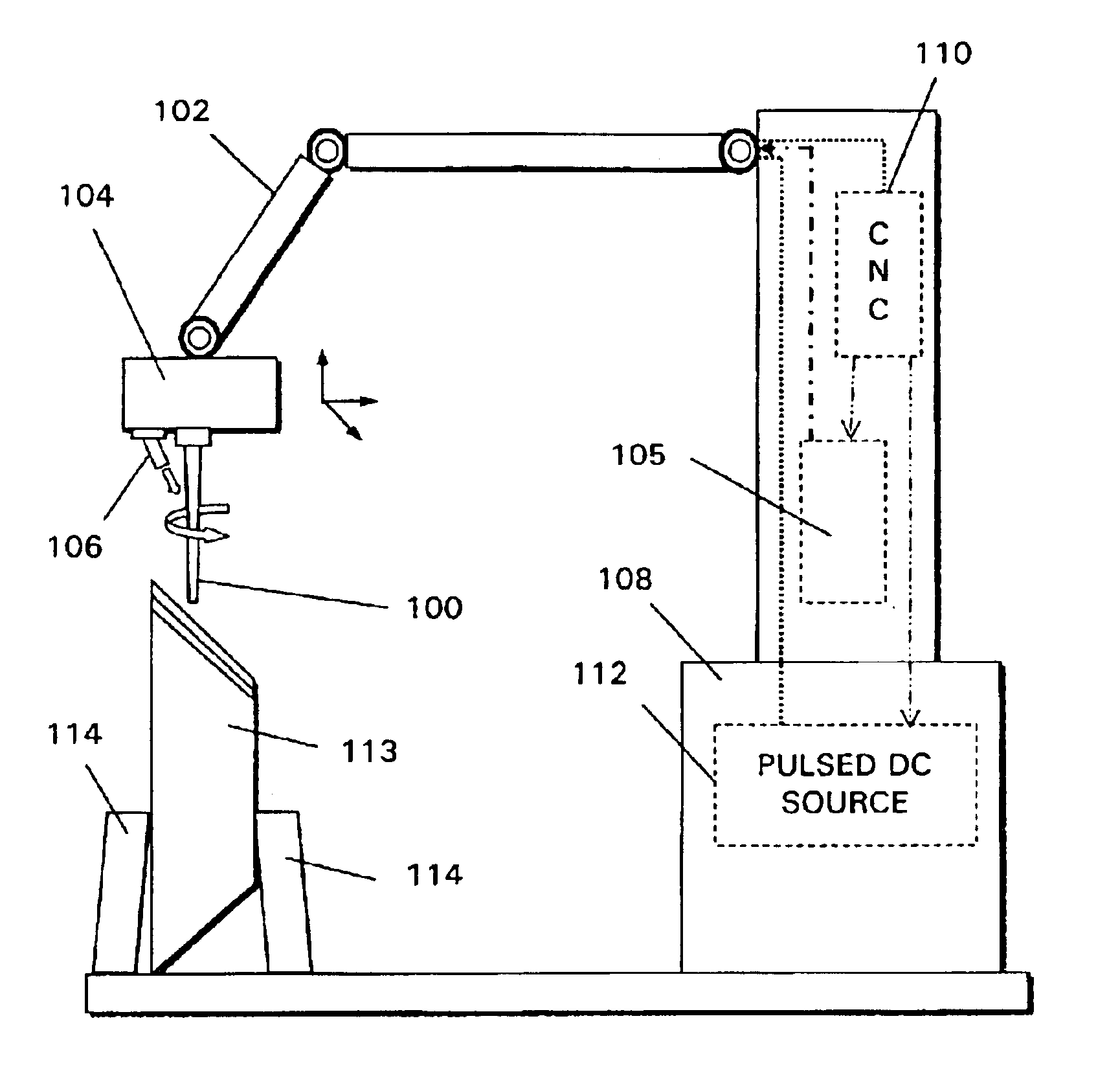
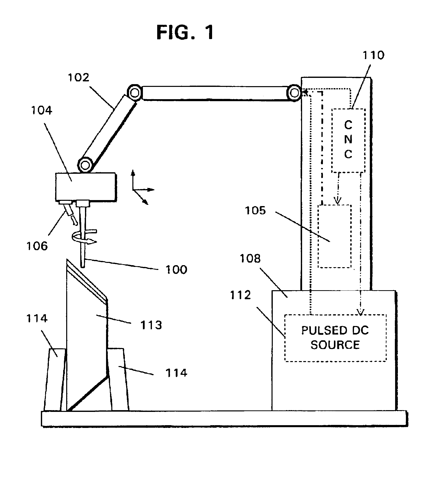
A first aspect of the invention resides in a multi-axis numerically controlled electromachining device comprising: a rotatable tool to induce controlled workpiece metal removal via high intensity, controlled electroerosion; and a numerical control device operatively connected with the tool to control movement of the tool about a plurality of axes to machine complex geometrical configurations.
A second aspect of the invention resides in a method of multi-axis numerically controlled electromachining comprising the steps of: rotating a tool to induce controlled workpiece metal removal via high intensity electro-thermal erosion; and moving the tool about a plurality of axes using a numerical control device operatively connected with the tool to machine complex geometrical configurations. The tool motion is strictly control based on the principle that highest metal erosion can be achieved with minimum workpiece thermal impact and with minimum surface recast layer or heat-affected zone caused by persistent arcing or short-circuiting.

Problems solved by technology

Due to electrical erosions on the machining surface, a large number of pits or craters are formed.
For blisks made of difficult to machine alloys such as IN718, the milling process typically has long cycle times, high cutting tool cost, and high equipment cost.
Additionally, long tool extensions necessary to reach into the machined pockets coupled with large cutting forces place limits on the rate and accuracy of material removal.
High speed milling adds significant equipment and tooling costs but has not shown great success in machining blisks made of tough nickel alloys.
One reason for the difficulty is the mechanical limitations imposed by a mechanical cutting process.
That is to say, a cutting tool having a moderate to high slenderness ratio can only tolerate a small load before tool deflection impacts accuracy of the milled product.
Additional loading may break the cutter.
Tool deflection also alters the tool's cutting geometry relative to the workpiece, leading to less than optimum performance in terms of tool life and accuracy of the milled product.
Mechanical loading is also limited by part deflection and desired accuracies.
Traditional NC EDM milling is a very slow process and it cannot meet the industrial need for high speed machining.

Method used


Image

  • Multi-axis numerical control electromachining of bladed disks
  • Multi-axis numerical control electromachining of bladed disks

Examples


Embodiment Construction

The present invention uses a high rate electroerosion in an electrolyte medium, to remove material and generate the desired shape and geometry.

Since non-mechanical means are used to remove and shape the material, low cost tools made of soft metals or any electrically conductive material can be used to significantly lower tooling costs. The workpiece metal removal rate can be increased by intense electrothermal actions, and no significant “cutting forces” are generated so that simple, low rigidity machines can be used that greatly reduce cost. Further, no compensation is necessary for tooling deflection that is common in mechanical milling.

As a non-mechanical process, the electro-machining speed is independent of workpiece material hardness and toughness. Higher metal removal speed than milling for tough workpiece metals can be achieved through high intensity electrothermal reactions.

With the present invention, it is possible to use soft metals as tool electrodes and the electrodes t...


PUM

PropertyMeasurementUnit
electrical poweraaaaaaaaaa
feed speedaaaaaaaaaa
erosion intensityaaaaaaaaaa

Abstract

A multi-axis machine, with numerical control on each axis, is used to drive the tool and workpiece movements necessary to machining complex airfoil geometry. Tooling is typically made of a metal such as brass or other low cost material and rotates during machining. The tooling may be any shape(cylindrical, conical) and size depending on application. A DC power (continuous or pulsed) is used to provide voltage across the tool and workpiece. A medium such as water, de-ionized water, or electrolyte (such as sodium nitrite) is provided between the tool and workpiece. Workpiece metal is removed in a controlled manner by high intensity thermal erosion.

Description

BACKGROUND OF THE INVENTIONThe present invention describes Electromachining and more specifically to an NC (Numerically Controlled) arrangement which can be used to machine complex shaped articles such as the airfoils on blisks to a near net shape at a high metal removal rate and with a low tooling cost as compared to turning, milling, EDM (Electro-Discharge Machining) or ECM (Electro-Chemical Machining).Electromachining is a technique which utilizes the rotating movement of a cylindrical shaped or similar profiled electrode(tapered) about the longitudinal axis with a profiled tip to remove material from a work piece. The kinematics of the machining is analogous to Numerical controlled milling. The electromachining is conducted with a rotating electrode. The tool-electrode is connected to the negative polarity, while the workpiece is connected to the positive polarity of a pulse generator. The pulse on-time may be of sufficiently long periods from hundreds of microseconds to seconds...

Claims


Application Information

Patent Timeline
Patent Type & Authority Patents(United States)
IPC IPC(8): B23H9/10B23H9/00B23H7/26B23H1/00B23H7/30B23H3/00B23Q15/00
CPCB23H1/00B23H3/00B23H9/10B23H7/30B23H2400/10
Inventor WEI, BINETHERINGTON, ROGERLAMPHERE, MICHAEL
Owner GENERAL ELECTRIC CO
Why Eureka
Eureka Blog
Learn More