Microlaboratory devices and methods

Inactive Publication Date: 2005-02-22
SRI INTERNATIONAL
View PDF21 Cites 111 Cited by
  • Summary
  • Abstract
  • Description
  • Claims
  • Application Information

AI Technical Summary

Benefits of technology

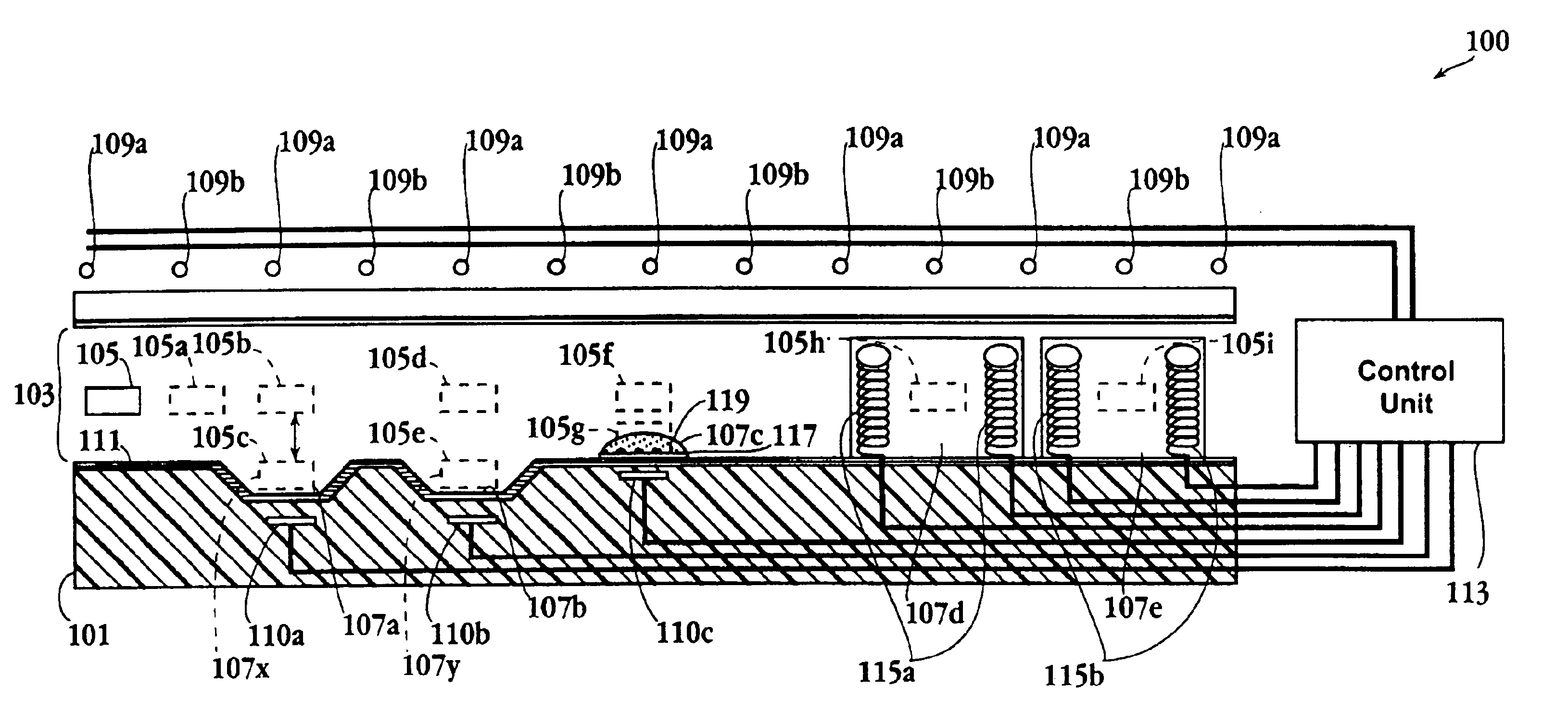
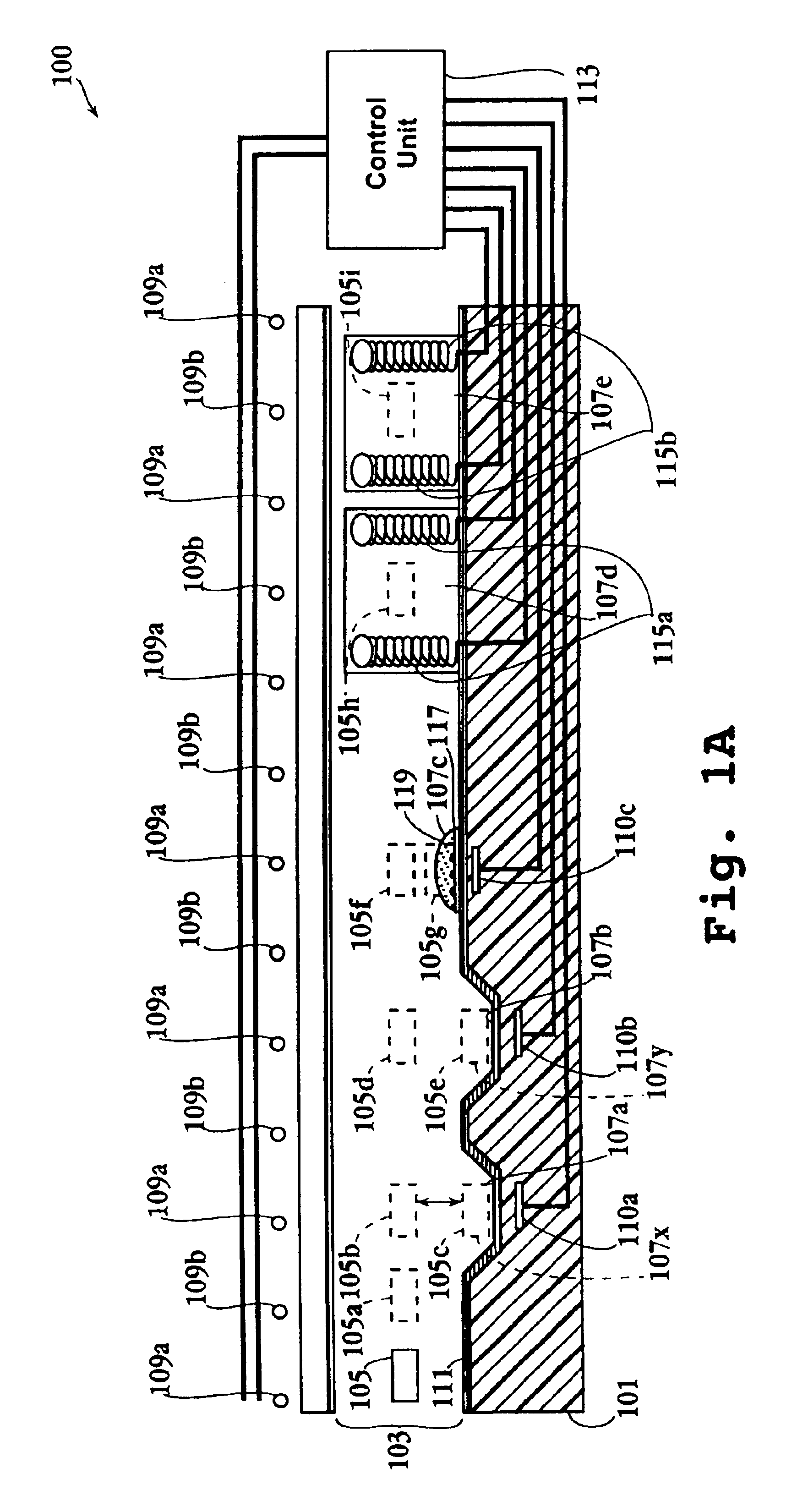
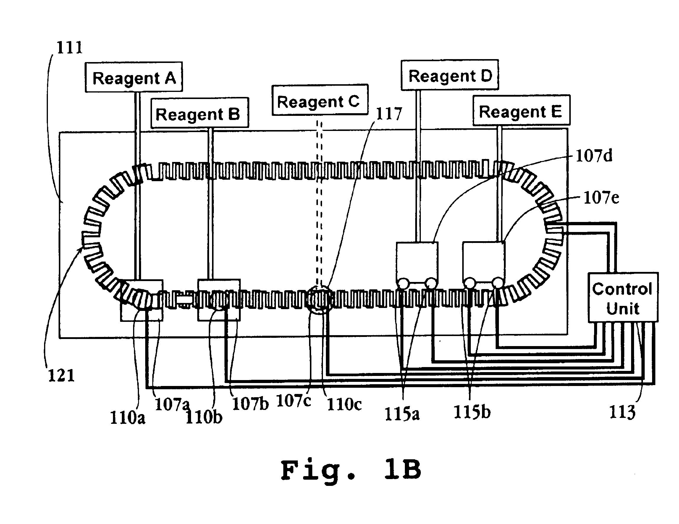
In yet other embodiments, at least some of the laboratory stations include a chamber for holding a selected liquid, and an chamber opening which defines a gas/liquid interface, when the chamber contains such liquid, said driving structure includes workstation drive elements which are effective, when energized, to move microparticles across the interface into

Problems solved by technology

These components have several potential drawbacks including clogging, inefficient pumping, viscous energy losses in the channels, inability to manipulate o

Method used


Image

  • Microlaboratory devices and methods
  • Microlaboratory devices and methods
  • Microlaboratory devices and methods

Examples


example 1

Functional PCR Test of DNA Attached to a Microparticle

Plasmid DNA at different concentrations was adsorbed to different, approximately 250 μm, rectangular silanized neodymium-iron-boron magnetizable microparticles in PCR buffer conditions. The microparticles were then independently washed, and then subjected to elution conditions using a high salt elution buffer. Aliquots of the liquid samples containing eluted DNA, if any, were transferred to independent PCR tubes. A cocktail of PCR primers, dNTPs and other PCR reagents were added to the tubes and PCR was performed. FIG. 35 depicts the results of the experiment demonstrating that DNA may be selectively acquired and released by a microparticle suitable for use in certain embodiments of the present invention.

example 2

Flow Chart for Use in Tuning Certain Embodiments

FIG. 36 depicts a flow chart useful in tuning system parameters for certain embodiments.

example 3

Size Specifications for an Embodiment Such as Depicted in FIG. 26

Driving Traces:

40 micron magnet wire8 mm wavelength, square wave pattern2 traces, offset 90 degrees spatially

Bias Traces:100 micron magnet wire2 mm inner diameter, 3.5 mm outer diameter, 6 turns (circuit with poppers)2.5 mm inner diameter, 4 mm outer diameter, 6 turns (linear track)2.8 mm (0.11″) above driving traces

Pop-Out Coils100 micron magnet wire7 mm outer diameter, 1 mm inner diameter, 1.5 mm thickfree standing coils; typical packing factor 70%See drawing for placement relative to pop-out reservoirs


PUM

PropertyMeasurementUnit
Orderaaaaaaaaaa
Dipoleaaaaaaaaaa

Abstract

Disclosed herein are apparatuses and devices, and methods for using and making the same, for use in performing desired activities in an automated, microscale format. Microparticles are ushered about within a microscale apparatus, to selectively move between various stations in a selected order and manner. Some embodiments include reaction, micro-weighing, micro-analysis, reagent acquisition and deposition, and incubation stations. Microparticles can individually move, or move as trains. Samples, including particulate and solid tissue samples may be manipulated and analyzed within the device. Some embodiments may engage in micro-fabrication activities or micro-deconstruction activities. Systems for controlling such apparatuses are included as well as methods of operation.

Description

FIELD OF THE INVENTIONThis invention relates to the fields of micro-fluidics, micro-scale machinery, chemical synthesis and analysis devices, medical and diagnostic devices, micro-machines, and lab-on-a-chip technology.BACKGROUNDExisting microfluidic systems typically rely on micro-scale pumps, channels, and / or electro-kinetic materials handling. These components have several potential drawbacks including clogging, inefficient pumping, viscous energy losses in the channels, inability to manipulate or tolerate particulates, and difficulty with high viscosity liquids. They also have system-level drawbacks. Each channel can generally carry only one high purity chemical without flushing. With only one chemical per channel, complex systems have routing and space difficulties. Further, at the reaction sites either valves or a constant positive outward flow are needed, to prevent back contamination.The present invention radically departs from pump-channel systems and addresses the drawback...

Claims


Application Information

Patent Timeline
IPC IPC(8): B01L3/00B01J19/00B81B1/00B81B7/02B01L99/00C12M1/00C40B40/06C40B40/10G01N35/00
CPCB01J19/0046B01L3/0293B01L3/50273B01L3/502738B01L3/502761B01J19/0093G01N35/0098B01J2219/00497B01J2219/005B01J2219/00549B01J2219/00563B01J2219/00587B01J2219/00596B01J2219/00605B01J2219/00612B01J2219/00617B01J2219/00619B01J2219/00621B01J2219/00626B01J2219/00628B01J2219/0063B01J2219/00637B01J2219/00644B01J2219/00653B01J2219/00655B01J2219/00659B01J2219/00689B01J2219/00722B01J2219/00725B01J2219/00743B01J2219/00871B01L2200/0647B01L2200/0657B01L2200/0668B01L2200/0673B01L2300/0816B01L2300/0838B01L2300/0867B01L2300/087B01L2300/088B01L2400/043B01L2400/0475B01L2400/0484B01L2400/0633C40B40/06C40B40/10G01N2035/00237
Inventor PELRINE, RONALD E.SHASTRI, SUBRAMANIAN VENKATJOSEPH, JOSE P.
Owner SRI INTERNATIONAL
Why Eureka
Try Eureka