Electrophoretic display and novel process for its manufacture

a technology of electrophoretic display and microencapsulation process, which is applied in the direction of static indicating device, separation process, instruments, etc., can solve the problems of difficult to keep different colors of suspensions from each other in the partition-type electrophoretic display, and the electrophoretic display manufactured by the microencapsulation process suffers from environmental changes sensitivity, etc., to achieve efficient and inexpensive production, high volume, and low cost

Inactive Publication Date: 2005-02-22
E INK CALIFORNIA
View PDF122 Cites 121 Cited by
  • Summary
  • Abstract
  • Description
  • Claims
  • Application Information

AI Technical Summary

Benefits of technology

These multiple-step processes as disclosed may be carried out roll-to-roll continuously or semi-continuously. Consequently, they are suitable for high volume and low cost production. These processes are also efficient and inexpensive as compared to other processes for high volume production operations. The electrophoretic display prepared according to the present invention is not sensitive to environment, particularly humidity and temperature. The display is thin, flexible, durable, easy-to-handle, and format-flexible. Since the electrophoretic display prepared according to the present invention comprises cells of favorable aspect ratio and well-defined shape and size, the bistable reflective display has excellent color addressability, high contrast ratio, and fast switching rate. The drawbacks of electrophoretic displays prepared by the prior art processes are therefore all eliminated.

Problems solved by technology

However, in the case of partition-type electrophoretic displays, some difficulties were encountered in the formation of the partitions and the process of enclosing the suspension.
Furthermore, it was also difficult to keep different colors of suspensions separate from each other in the partition-type electrophoretic display.
For example, the electrophoretic display manufactured by the microencapsulation process suffers from sensitivity to environmental changes (in particular, sensitivity to moisture and temperature) due to the wall chemistry of the microcapsules.
Secondly, the electrophoretic display based on the microcapsules has poor scratch resistance due to the thin wall and large particle size of the microcapsules.
To improve the handleability of the display, microcapsules are embedded in a large quantity of polymer matrix which results in a slow response time due to the large distance between the two electrodes and a low contrast ratio due to the low payload of pigment particles.
It is also difficult to increase the surface charge density on the pigment particles because charge-controlling agents tend to diffuse to the water / oil interface during the microencapsulation process.
The low charge density or zeta potential of the pigment particles in the microcapsules also results in a slow response rate.
Furthermore, because of the large particle size and broad size distribution of the microcapsules, the prior art electrophoretic display of this type has poor resolution and addressability for color applications.

Method used


Image

  • Electrophoretic display and novel process for its manufacture
  • Electrophoretic display and novel process for its manufacture
  • Electrophoretic display and novel process for its manufacture

Examples


example 1

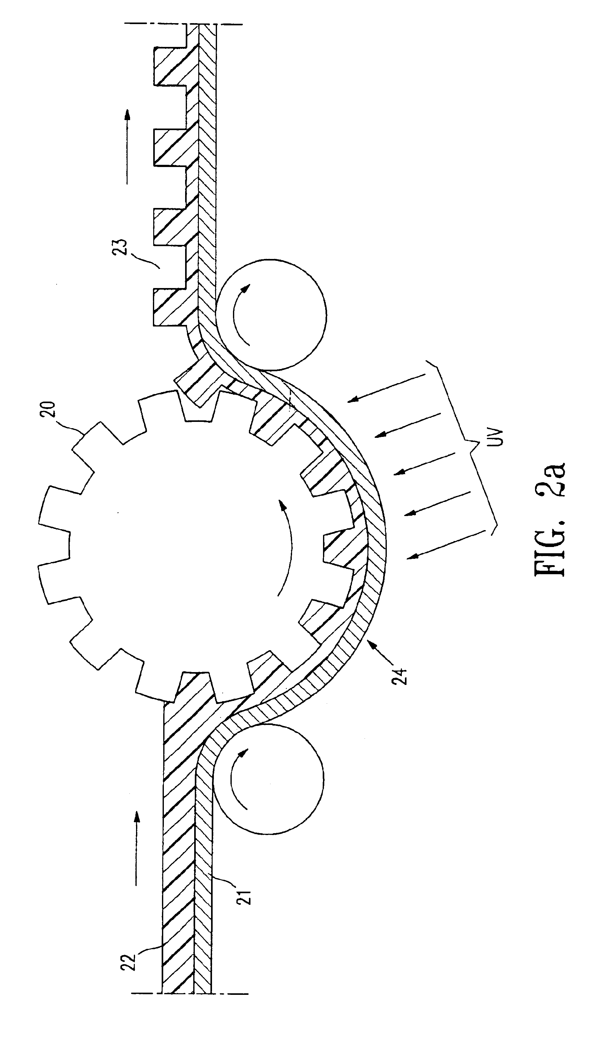
Preparation of Microcups by Microembossing

The composition shown in Table 1 is coated onto Mylar J101 / 200 gauge using a Nickel Chrome bird type film applicator with an opening of 3 mil. The solvent is allowed to evaporate leaving behind a tacky film with a Tg below room temperature.

TABLE 1PMMA-containing composition for microembossingNo.DescriptionIngredientSupplierWt %1Epoxy acrylateEbecryl 3605UCB Chemicals7.352MonomerSartomer SR205Sartomer9.593Urethane acrylateEbecryl 6700UCB Chemicals4.874Polymethyl-Elvacite 2051ICI9.11methacrylate5PhotoinitiatorDarocur 1173Ciba1.456CationicCyracure UVIUnion Carbide0.60photoinitiator69767SolventAcetoneAldrich67.03Total100.00

A pre-patterned stencil from Photo Stencil, Colorado Springs, Colo., was used as the male mold for microembossing and Frekote 700-NC from Henkel was used as the mold release. The coated film was then embossed by the stencil using a pressure roller at room temperature. The coating was then UV cured for about 20 minutes through ...

example 2

A composition containing solid oligomer, monomer and additive is shown in Table 2. The glass transition temperature of the mixture is again below room temperature. The tacky coating is deposited on top of Mylar J101 / 200 gauge as before. Embossing can be conducted at 32° C. and 60° C. using a heated pressure roller or laminator. Well-defined high resolution microcups (100-400 dpi) with depth ranging from 5-30 microns were produced.

TABLE 2Embossing composition containingoligomer, monomer, additive and solventNo.DescriptionIngredientSupplierWt %1Epoxy acrylateEbecryl 3903UCB Chemicals17.212MonomerHDODAUCB Chemicals8.613Urethane acrylateEbecryl 4827UCB Chemicals2.874PhotoinitiatorIrgacure 500Ciba1.435SlipEbecryl 1360UCB Chemicals1.606SolventAcetoneAldrich68.26Total100

example 3

Preparation of Pigment Dispersion in Dielectric Solvent

Polystyrene (0.89 grams, Polysciences, Inc., mw. 50,000) and AOT (0.094 grams, American Cyanamide, sodium dioctylsulfosuccinate) were dissolved in 17.77 grams of hot xylene (Aldrich). Ti-Pure R-706 (6.25 grams) was added to the solution and ground in an attritor at 200 rpm for more than 12 hours. A low viscosity, stable dispersion was obtained. Oil-blue N (0.25 grams, Aldrich) was added to color the dispersion. The suspension was then tested in a standard electrophoretic cell comprising two ITO conductor plates separated by a 24 microns spacer. High contrast, alternating white and blue images were observed with a switching rate of about 60 Hz and a rising time of 8.5 msec at 80 volts.


PUM

PropertyMeasurementUnit
areaaaaaaaaaaa
areaaaaaaaaaaa
depthaaaaaaaaaa

Abstract

This invention relates to an electrophoretic display comprising cells of well-defined shape, size and aspect ratio which cells are filled with charged pigment particles dispersed in a solvent, and novel processes for its manufacture.

Description

BACKGROUND OF THE INVENTIONa) Field of the InventionThis invention relates to an electrophoretic display comprising cells of well-defined shape, size and aspect ratio, which cells are filled with charged pigment particles dispersed in a solvent, and novel processes for its manufacture.b) Description of Related ArtThe electrophoretic display is a non-emissive device based on the electrophoresis phenomenon of charged pigment particles suspended in a solvent. It was first proposed in 1969. The display usually comprises two plates with electrodes placed opposing each other, separated by using spacers. One of the electrodes is usually transparent. A suspension composed of a colored solvent and charged pigment particles is enclosed between the two plates. When a voltage difference is imposed between the two electrodes, the pigment particles migrate to one side and then either the color of the pigment or the color of the solvent can be seen according to the polarity of the voltage differen...

Claims


Application Information

Patent Timeline
Patent Type & Authority Patents(United States)
IPC IPC(8): G02F1/01G02F1/167G02F1/13G02F1/1339G02F1/1333G01N27/447
CPCB29C39/06G02F1/167B29C39/026G02F1/133305G02F1/133377G02F1/1339G02F1/16755G02F1/1679
Inventor LIANG, RONG-CHANGCHAN-PARK, MARYTSENG, SCOTT C-JWU, GEORGEZANG, HONGMEI
Owner E INK CALIFORNIA
Why Eureka
Try Eureka