Grout compositions for construction of subterranean barriers

a technology of subsurface containment and composition, which is applied in the direction of gaskets, coatings, nuclear engineering, etc., can solve the problem of heavy weight of proprietary fluid, achieve good bonding and encapsulation of organic sludge, and adjust the temperature of the material quickly

Inactive Publication Date: 2005-03-01
CARTER JR ERNEST E
View PDF48 Cites 19 Cited by
  • Summary
  • Abstract
  • Description
  • Claims
  • Application Information

AI Technical Summary

Benefits of technology

The grout material may be either a slow setting dense material capable of buoyantly supporting the overburden or may be a fast set or thermoplastic set material which sets before a large unsupported span exists. A low water, cementitious, latex polymer modified grout with iron oxide additives and a long term set retarder is preferred for buoyant barriers. A molten grouting material made from paraffin wax or polyethylene homopolymer and surfactant admixtures which enable it to mix with damp or wet soils and permeate farther into water impermeable soils is preferred for the non-buoyant process. Circulation of molten grout through the pulling pipes and the catenary tube can keep the material from setting during a work delay or even overnight. Paraffin supply lines from relatively hot and relatively cool but molten paraffin may be blended by a valve to rapidly adjust the temperature of the material with changing ground conditions. Blends of paraffin and polyethylene may also be used. A cap liner made of a similar polyethylene or paraffin mixture may be used in the top cap and heat fusion bonded to the bottom barrier to create a completely air tight seal of similar material. This cap material may be sprayed onto the surface of the cap as a liquid material and cured in place or it may be a pre-fabricated sheet.
The above mentioned grouts have desirable properties for block encapsulation of buried low level radioactive waste. The molten wax and surfactant blends offer superior permeation into non-homogenous trash as well as good bonding and encapsulation of organic sludges. They offer a desirable matrix to stabilize the waste while it remains in the ground and also prevent airborne dust release during future retrieval. Since they are fully combustible they add no volume to the final waste matrix of a vitrification melter process.

Problems solved by technology

This proprietary fluid is so heavy that the soil and rock will literally float on a thin layer of the fluid.

Method used


Image

  • Grout compositions for construction of subterranean barriers
  • Grout compositions for construction of subterranean barriers
  • Grout compositions for construction of subterranean barriers

Examples


Embodiment Construction

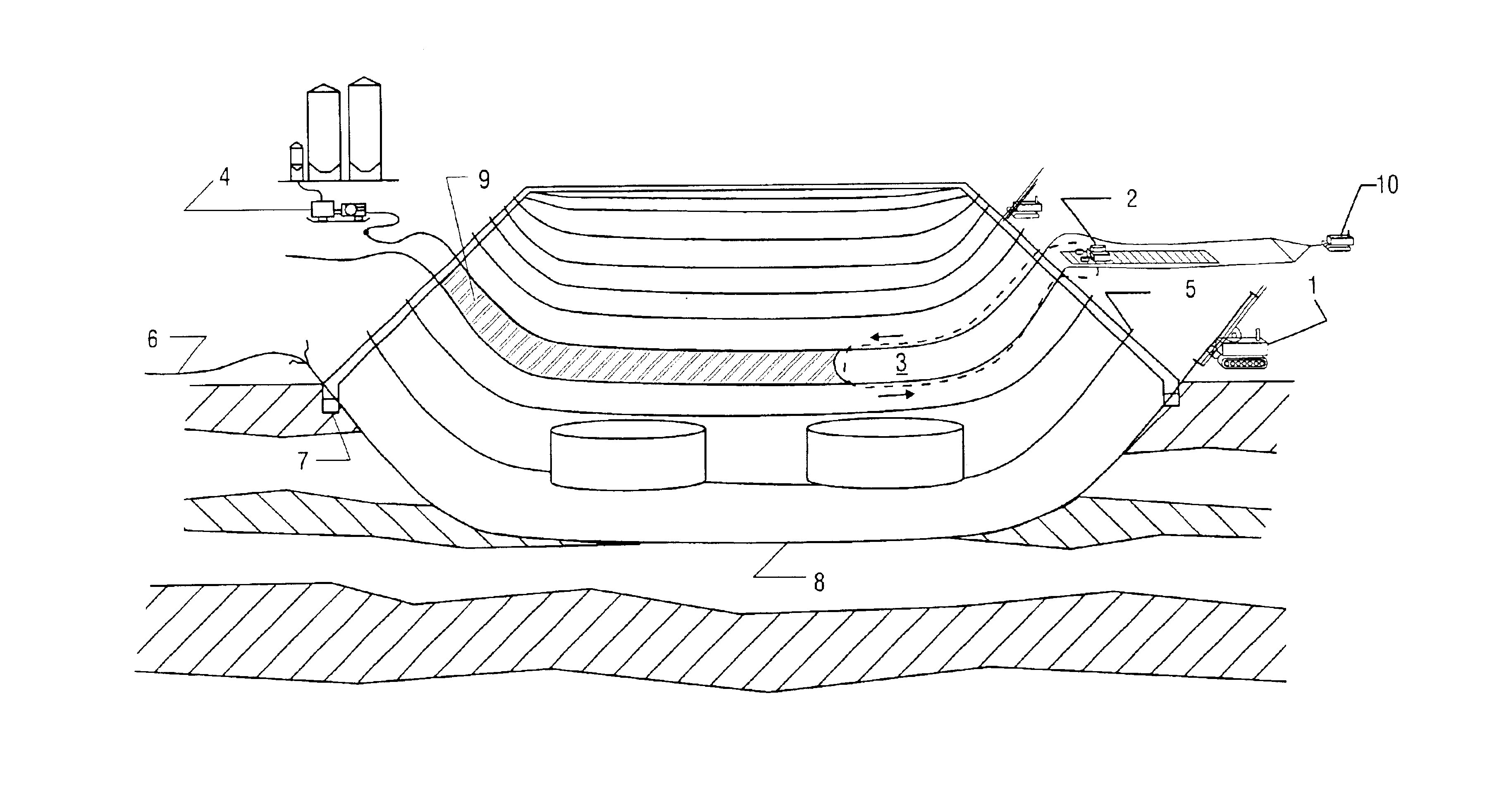
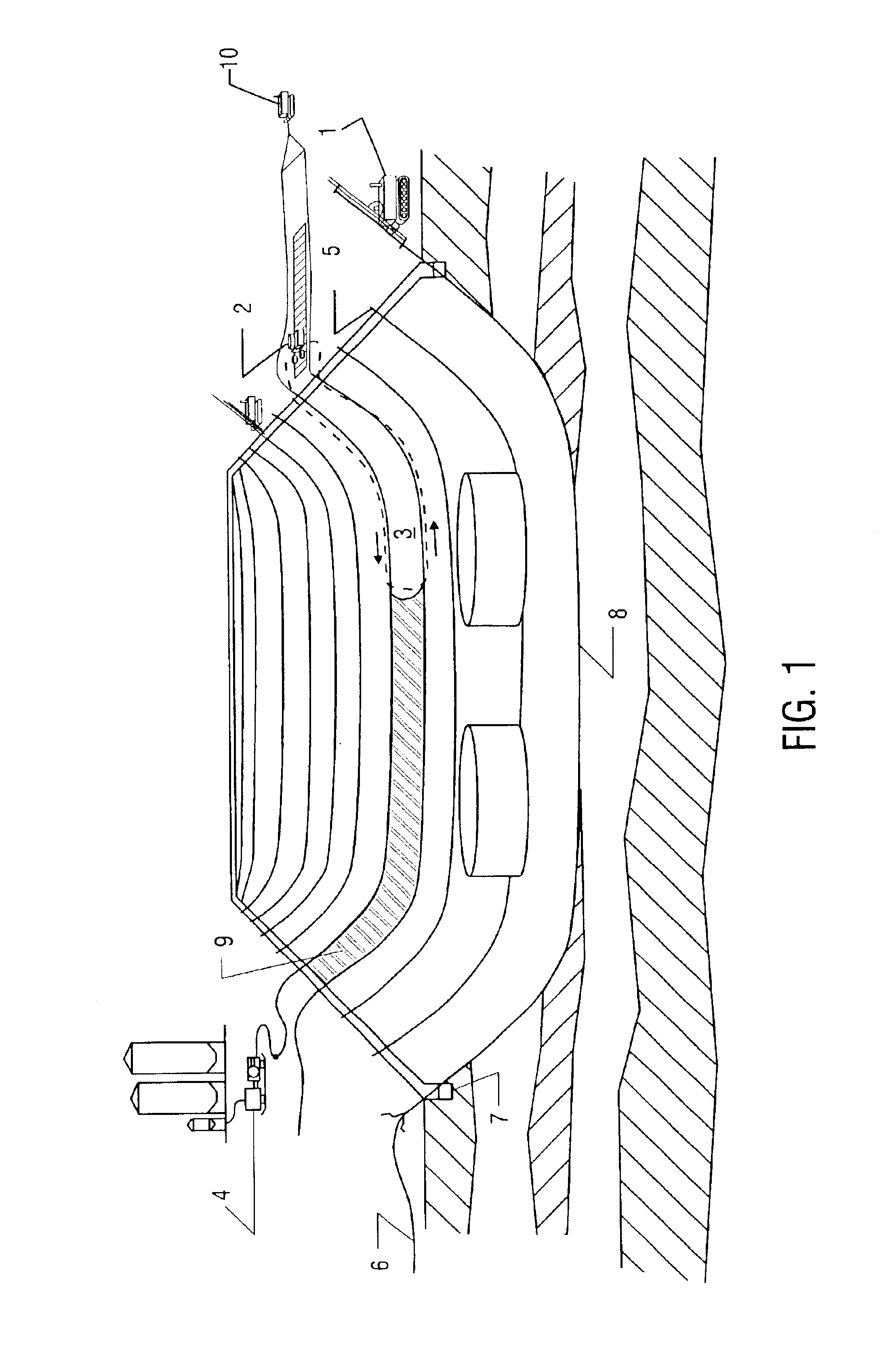
Referring to FIG. 1, a shallow perimeter trench 7 is first excavated around the entire surface perimeter of the block to be isolated. A subsurface “block” or volume of the eat is defined by the ground level on its top and by a bottom comprised of a box-shaped or basin-shaped three dimensional mathematical “surface” which surrounds and underlies the block and rises upward to the ground level at the perimeter, forming a complete and continuous basin, fully enclosing the volume of earth.

A directional drilling machine 1 then drills rows of pilot holes under the site, which define the basin's elongated shape. A pulling pipe with two or more non-crossed cables strapped to it is connected to the drill pipe and pulled through the pilot holes. After this operation each pilot hole contains a pulling pipe and two or more color coded steel cables. Next, a diamond-wire saw machine 2 moves an abrasive cable 3, formed by joined adjacent cables, through the pilot holes cutting a pathway between adj...


PUM

PropertyMeasurementUnit
densityaaaaaaaaaa
melting pointaaaaaaaaaa
barrier thicknessaaaaaaaaaa

Abstract

A method is disclosed for constructing, verifying, and maintaining underground vaults that isolate and contain radioactive burial sites. The method employs a buoyant lift technique to isolate a block of soil containing the contaminates from the surrounding soil. An impermeable synthetic liner is embedded in the vault to enhance the integrity of the system. The integrity of the vault is monitored by a system of sensors placed both inside and outside of the sealed vault. The method eliminates the need to excavate or drill in the contaminated areas.

Description

FIELD OF THE INVENTIONThe present invention relates generally to apparatus and methods for in situ construction of subsurface containment barriers for containing hazardous waste materials buried under the earth, and more particularly to a method of constructing a vault to encapsulate such hazardous materials so that contaminants are not released into the air or surrounding or underlying strata. The present invention further relates to a means for monitoring the continued integrity of the vault over many years and to a means for repairing any breaches which might occur over time.BACKGROUND OF THE INVENTIONIn the early days of the nuclear age, contaminated debris and undocumented low level radioactive waste were buried in shallow trenches. Other waste materials were placed in underground storage tanks. These burial areas are now considered to pose a unacceptable risk to the environment. Excavation and removal of these wastes is potentially dangerous and very expensive. The concern is ...

Claims


Application Information

Patent Timeline
Patent Type & Authority Patents(United States)
IPC IPC(8): B09B1/00E02D31/00G21F9/34E02D5/20C04B28/04C04B111/70
CPCB09B1/00E02D31/00G21F9/34Y10S106/90E02D2600/10E02D2450/105
Inventor CARTER, JR., ERNEST E.
Owner CARTER JR ERNEST E
Why Eureka
Try Eureka