Hybrid composite articles and methods for their production

a hybrid composite and composite article technology, applied in colloidal chemistry, light beam reproducing, instruments, etc., can solve the problems of difficult suppression, difficult to obtain a uniform matrix between the fibers, and difficult to obtain thermoset composites, etc., to prolong the stability time, stable emulsion, and small dimensions

Inactive Publication Date: 2005-03-01
COMPLASTIK CORP
View PDF79 Cites 34 Cited by
  • Summary
  • Abstract
  • Description
  • Claims
  • Application Information

AI Technical Summary

Benefits of technology

FIG. 2 illustrates the disadvantageous effects in forming a composite through an emulsion process if an unstable emulsion is used. FIG. 2 shows a schematic cross-section of a portion of a strand 50 comprising a collection of continuous fibers 52. FIG. 2A shows strand 50 immediately upon exposure to an unstable emulsion 54. The emulsion on strand 50 is no longer exposed to agitation conditions such as continuous stirring or shaking. Thus, particles of emulsion 54 settle and deposit on strand 50 as a layer 56 of loose powder. FIG. 2B shows a partly dried strand in which layer 56 grows denser as more particles settle from suspension. Some of the powder may penetrate outer fibers 52a of the strand, provided the particle size is sufficiently small, but due to the settling of the powder, the particles lose mobility to penetrate inner fibers 52b of strand 50. FIG. 2C shows a final prior art 58 prepreg in which a dense layer of particles 56 coats the outside of strand 50 and fails to penetrate below the outer surface.
in forming a composite through an emulsion process if an unstable emulsion is used. FIG. 2 shows a schematic cross-section of a portion of a strand 50 comprising a collection of continuous fibers 52. FIG. 2A shows strand 50 immediately upon exposure to an unstable emulsion 54. The emulsion on strand 50 is no longer exposed to agitation conditions such as continuous stirring or shaking. Thus, particles of emulsion 54 settle and deposit on strand 50 as a layer 56 of loose powder. FIG. 2B shows a partly dried strand in which layer 56 grows denser as more particles settle from suspension. Some of the powder may penetrate outer fibers 52a of the strand, provided the particle size is sufficiently small, but due to the settling of the powder, the particles lose mobility to penetrate inner fibers 52b of strand 50. FIG. 2C shows a final prior art 58 prepreg in which a dense layer of particles 56 coats the outside of strand 50 and fails to penetrate below the outer surface.
Thus, from FIG. 2, it can be understood that with a stable emulsion, particles can be maintained in suspension even when adhered to a strand, i.e. when not exposed to agitation conditions. Particles in a suspension have sufficient mobility to penetrate to fibers of the strand and substantially fill gaps between individual fibers. In some cases, after initially exposing the fibers to the stable emulsion followed by penetration of particles into the strand, additional re-exposure steps may be required to provide sufficient amounts of polymer particles to coat and substantially fill in the gaps of the innermost fibers.
Thus, an advantageous feature of the present invention allows the individual fibers to be impregnated with polymer particles in the absence of high pressures, thus avoiding certain prior art methods of forcing polymer melts under pressure into the gaps between the fibers. The strand can be exposed to the stable emulsion in any manner that “wets” the strand with a sufficient amount of the emulsion. The exposing can occur by immersing or dipping the strand in the emulsion, spraying the strand with the emulsion, painting the strand, or any other wetting means. Because the particles in the emulsion have sufficiently small dimensions, simply exposing the strand to the emulsion allows particles to impregnate the gaps between individual fibers.
In one embodiment, the stable emulsion is provided by controlling the “solids content” of the emulsion. Polymer particles typically make up the vast majority of the “solids content.” An optimal solids content for a particular polymer type can depend on the polymer particle size, viscosity of the dispersant, temperature of the emulsion and / or the presence of other additives such as surfactants or stabilizers. Stabilizers are added to the emulsion to extend the time of stability and are usually polymers that are soluble in the dispersant and thicken the dispersant Generally, the solids content of the emulsion is sufficiently high to maintain a viscous dispersion which inhibits settling of the particles. If the solids content is too high, however, the consistency of the emulsion resembles more of a paste (as opposed to a “cream”) and solids can coagulate to larger aggregates, leading to settling. In these embodiments, the stable emulsion of the present invention has a solids content of no more than about 60%. In other embodiments, the emulsion can have a solids content of no more than about 50% or even as low as no more than about 30%. Optimally, the emulsion has a solids content of at least about 5% to about 60%. Depending on factors such as polymer type and fiber type, the emulsion can have a solids content from about 5% to about 50%, from about 5% to about 45%, from about 5% to about 30%, from about 30% to about 60%, from about 30% to about 50%, or from about 30% to about 45%.
In one embodiment the mean diameter of the polymer particles can be used to maintain a stable emulsion. The range of mean diameters for a particular polymer can depend on factors such as solvent viscosity, e.g. more viscous solvents can suspend larger particles and thus the range is greater. Desired particle diameters will also depend on other factors besides maintaining a stable emulsion, such as the diameter of the individual fibers to be used in the composite (see discussion of FIG. 5) or any of the other factors mentioned above. In another embodiment, the particles have an average diameter of less than 5 μm, preferably less than about 1 μm, more preferably less than about 0.5 μm, and more preferably still, less than about 0.25 μm.

Problems solved by technology

As the volume of fiber in the composite increases, however, obtaining a uniform matrix between the fibers tends to be more difficult.
Thermoset composites suffer from several disadvantages, however.
These low pressures, however, make it difficult to suppress the formation of bubbles within the composite which can result in voids or defects in the matrix coating.
Thus, most processing problems with thermoset composites are concerned with removing entrained air or volatiles so that a void-free matrix is produced.
Thermoset polymers are not easy to process, regardless of whether the resin is applied to the yarns before molding or is infused into a preform of fibers.
Although thermoset polymers have enjoyed success as in lower performance composites, the difficulties in processing these resins has restricted their application, particularly for high performance use.
Causing melt flow of highly viscous thermoplastics requires the application of high temperatures and / or pressures which can be inherently destructive to the fibers, resulting in fiber damage or distortion.
This process can suffer the disadvantages of melt flow as described above.
The long pathway from the outside of the strand to the gaps between the fibers renders filling these gaps highly unlikely.
Again, melt flow is required to form the matrix, and a void-free matrix is not assured.
Removal of solvent presents extra processing problems, however.
Separate yarns of thermoplastic and reinforcement containing many thousands of filaments, however, cannot be mixed mechanically in a one-by-one arrangement of each fiber.
In addition, mere coating of strands inherently results in an insufficient amount of polymer to form a void-free matrix.
In general thermoplastic composites have had limited success to date, due to a variety of factors including high temperatures, high pressures, and prolonged molding times needed to produce good quality laminates.

Method used


Image

  • Hybrid composite articles and methods for their production
  • Hybrid composite articles and methods for their production
  • Hybrid composite articles and methods for their production

Examples


example 1

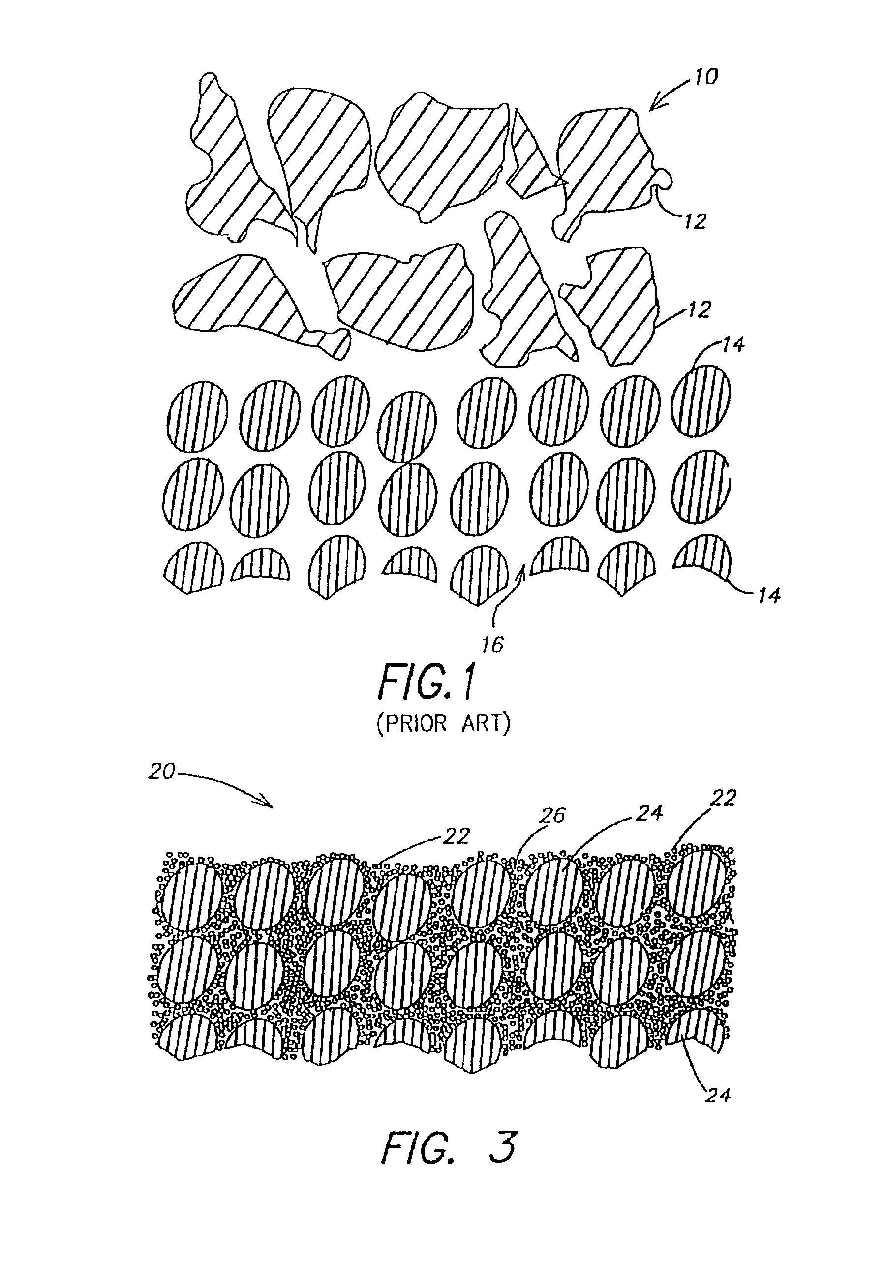
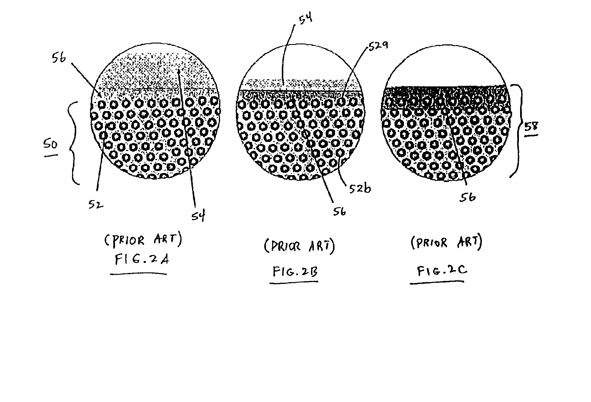
A styrene / acrylic copolymer emulsion (SA 204 from Para-Chem Inc.) was selected because of its properties. The polymer has a Tg (glass transition temperature) of around 200° F. if prepared by non-emulsion methods. If prepared by emulsion polymerization, SA204 has a Tg of 50° F. The latex has particles around 200 nanometers in size.

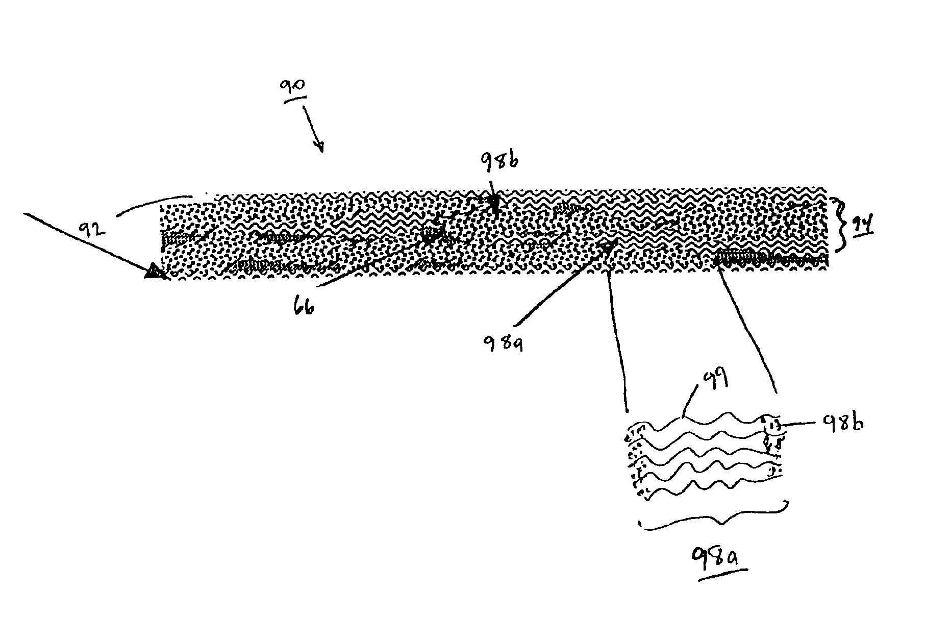
Glass fabrics are coated generously by immersing the fabrics in the emulsion and allowed to air dry for 16 hours. Once they are essentially dry, the sheets of prepreg are covered each side with a nylon film. The film coated prepreg is then pressed with a smoothing iron set at 200° F. (93° C.) resulting in a fusing of the particles. (Small latex particles will fuse when taken above their glass transition temperature without melting).

Subsequently, the prepreg sheets are press molded into high quality laminates. Prepreg layers are stacked in the desired orientation and heat tacked together to maintain that orientation. The stack is then loaded into a preheated...

example 2

Table 1 shows the strength properties of example fibrous articles of the present invention. All properties are normalized to 60% fiber by volume. The fabrics in Table 1 are all 18 oz non-woven, stitched glass fabric with equal 0° and 90° fibers (BTI's 1800 style). The fabrics were coated with a thermoplastic latex as described in Example 1. The coating was dried at 250° F. (121° C.) for 30 minutes. Eight plies of the prepreg were then pressed together with each layer laid up in the same direction. The plies were pressed together under 100 psi pressure at 360° F. (182° C.).

TABLE 1Fiber composite propertiesApparentFlexuralThermoplasticManufacturerApparent FlexuralModulustype(Thermoplastic number)Strength (ksi)(msi)VinylAir Products, Inc.68.82.66acetate / Acrylic(Vancryl 989)AcrylicParachem71.23.60(Paracryl 8444)Styrene / AcrylicParachem77.42.93(SA-204)AcrylicPolymer Latex Corp.54.62.70(Rohamere 4010D)

example 3

Continuous graphite fiber tows (strands) are dipped into a bath of SA 204 latex while being spread over a plexiglass bar. The tows are then passed through a tube oven with a wall temperature of 550-650° F. (288-343° C.). The tow spends about 30 seconds in the oven while the water is flashed off and the latex particles are fused. As it exits the oven, the tow is passed through rollers to flatten it to a uniform thickness. Single tows can be treated (towpreg) or collimated groups of tows can form tapes. Tape and towpreg forms of the thermoplastic composite lend themselves to automated molding processes such as hot winding and automatic fiber placement. Sheets of the tape can be stacked in controlled orientations and pressed into useful laminates with the same press cycle as described above for glass prepregs.


PUM

PropertyMeasurementUnit
pressureaaaaaaaaaa
pressureaaaaaaaaaa
mean diameteraaaaaaaaaa

Abstract

The present invention relates to high quality composite materials from fibrous materials, in which the composite incorporates a polymer matrix embedding individual fibers. The matrix is derived from polymer particles which penetrate into a strand and substantially fill gaps between individual fibers. Such penetration can occur by exposing the strand to a stable emulsion of the polymer particles. The invention also relates to novel composite structures which incorporation of various types of fibrous segments. These composite structures allow the use of inexpensive and readily available scrap materials. The composites of the present invention are lightweight materials displaying enhanced strength and durability.

Description

FIELD OF INVENTIONThe present invention relates to hybrid composite articles such as fiber resin composites, and particularly inexpensive composites made from scrap or surplus fibers. The composites comprise a polymer matrix embedding individual fibers, as derived from composite prepregs having a coating of polymer particles substantially filling gaps between the individual fibers. The invention further relates to methods for making such composite articles, such as the use of a stable emulsion with polymer particles of sufficiently small size to penetrate gaps between individual fibers. The invention also relates to other composite articles in which a porous material has a polymer matrix embedded within pores of the material.BACKGROUND OF THE INVENTIONThere has been a long-felt need for lightweight fiber-resin composite materials which display greater strength than currently known composites. Fiber resin composites include fibrous articles, sheets and strands (tows or yarns) which i...

Claims


Application Information

Patent Timeline
Patent Type & Authority Patents(United States)
IPC IPC(8): B29B15/10B29B15/12B29C70/04B29C70/46C08J5/24C08J11/06
CPCB29B15/122B29C70/465C08J11/06C08J5/24Y10T428/26Y10T428/25B29B15/12Y10T428/249986Y10T428/249924Y10T428/249953Y02W30/62C08J5/244C08J5/243
Inventor EVANS, DAVID A.
Owner COMPLASTIK CORP
Why Eureka
Try Eureka