System for determining position of an emitter

a technology for estimating systems and emitters, applied in direction finders using radio waves, instruments, navigation instruments, etc., can solve the problems of increasing size and cost, reducing mobility, and complicated task of estimating the position of emitter devices, so as to maximize the use of commercially available hardware, minimize design and manufacturing costs, and high accuracy

Inactive Publication Date: 2005-03-01
EXCELIS INC
View PDF25 Cites 170 Cited by
  • Summary
  • Abstract
  • Description
  • Claims
  • Application Information

AI Technical Summary

Benefits of technology

The invention disclosed herein provides a highly accurate emitter position estimating system capable of locating both fixed and mobile emitters, in real time, regardless of the nature of the signal emitted. Detection of emitted signals can be performed by modularly replaceable software and/or hardware units that may include state-of-the-art, commercial off the shelf (COTS) software and/or hardware, digital signal processors (DSP), field programmable gate arrays (FPGA), and application specific integrated circuits (ASICS). These modularly replaceable units allow a receiver device to be specifically tailored and/or reprogrammed, as necessary, to meet specific operational signal detection requirements, and to modularly adapt to changes in signal transmission and/or detection techniques. The emitter position estimating capability disclosed herein as part of the present invention, however, is independent of the emitted signal detection technology used by the respective receiver devices. The position estimating technique disclosed herein as part of the present invention remains effective for estimating the position of emitted signal regardless of the signal detection technologies used.
The invention minimizes design and manufacturing costs by maximizing use of commercially available hardware and software such as inexpensive, low accuracy clocks, spread spectrum communication hardware, and proven, efficient network protocols. The emitter position estimating capabilities described herein can be transparently integrated within compact, handheld or portable, multi-purpose communication devices, thereby allowing widespread deployment at minimal incremental cost. Detection and position

Problems solved by technology

Where an emitter is not directly cooperating with devices attempting to determine the emitter's position, the task of estimating the position of an emitter device is complicated by the fact that the emitter must be located without the benefit of two way communications.
Unfortunately, this technique is reliable and accurate only if the transmitter is fixed and the emitted signal is sustained over a sufficient period of time to be tracked.
Although an antenna array provides an improvement over using multiple antennas, it requires a bulky phased array antenna which increases size and cost and decreases mobility.
Other existing techniques use extensive post processing to reduce a wealth of data into position information; however, these techniques also involve bulky and cumbersome equipment and/or fail to provide real time solutions.
As a whole, existing approaches suffer from a multitude of deficiencies which include: the inability to detect a broad range of emitted signal types; the inability to adapt to changes and advancements in tec

Method used


Image

  • System for determining position of an emitter
  • System for determining position of an emitter
  • System for determining position of an emitter

Examples


Embodiment Construction

The following detailed explanation of the figures and of the preferred embodiments of the present invention reveal the methods and apparatus of an emitter position estimating system capable of accurately determining the position of an electromagnetic signal emitter using time-synchronized receiver radios equipped with cost effective, low accuracy clocks.

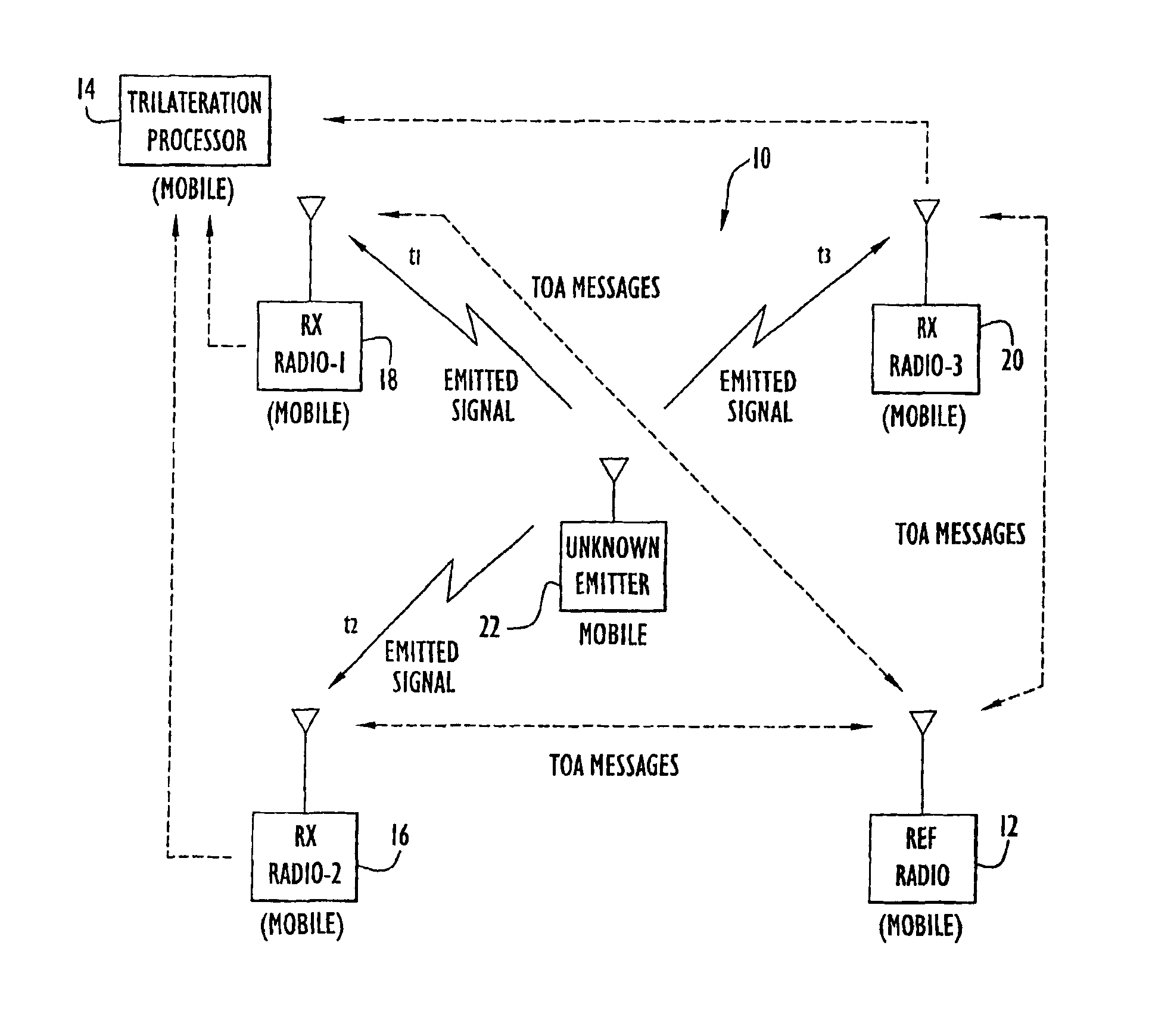
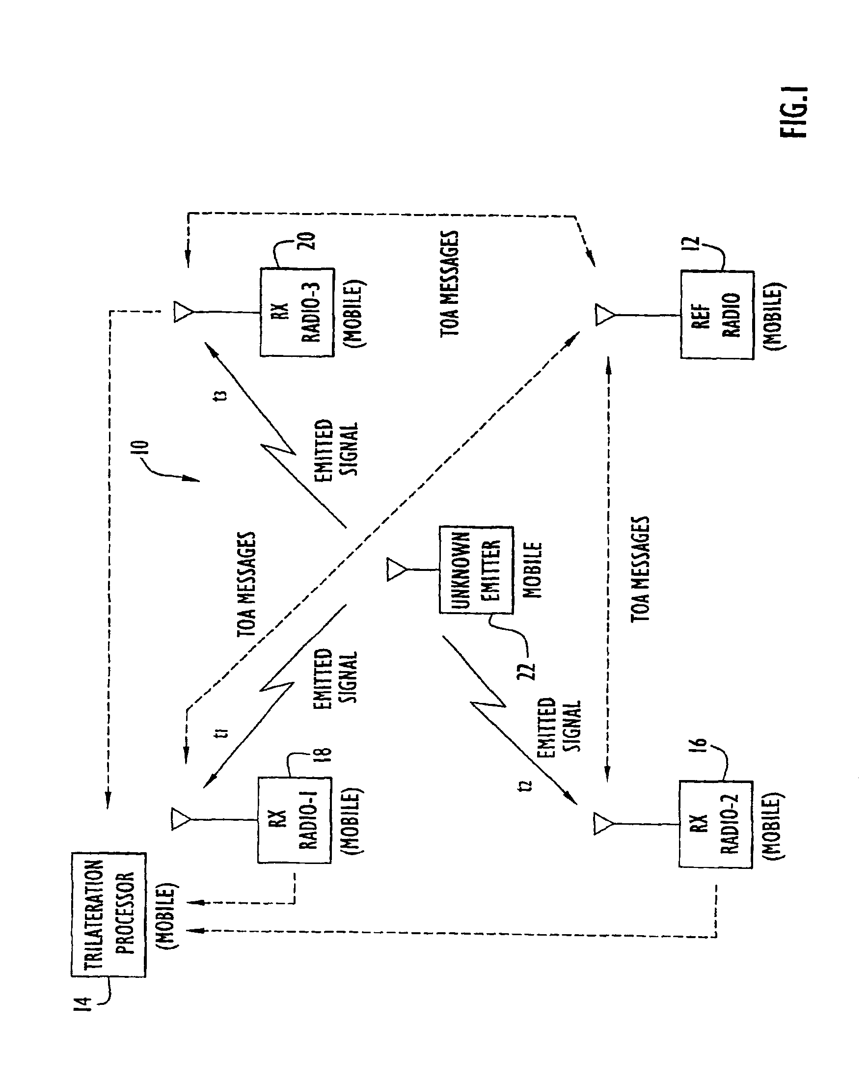
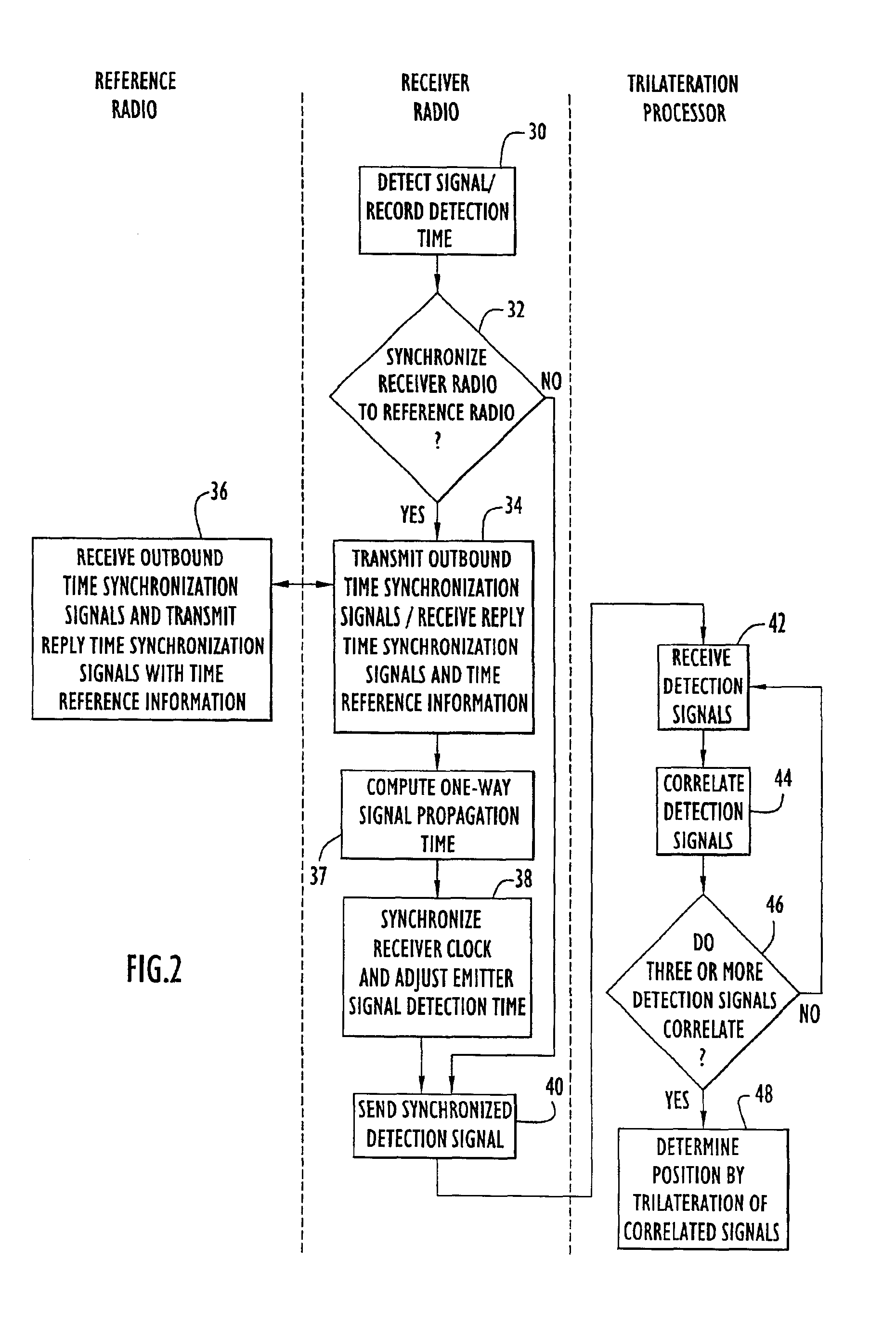
An exemplary embodiment of the present invention is represented in FIG. 1 with a diagrammatic functional view and is represented in FIG. 2 with a functional process flow view. As indicate in both figures, the process of estimating the position of an emitter using the techniques disclosed in the present invention begins with the detection of an emitted signal from an unknown emitter. In FIG. 1, receiver radios 16, 18, and 20 detect an emitted signal from an unknown emitter 22. In FIG. 2, which presents a unified process flow of events, detection of an emitted signal by all three receiver radios is represented in step 30. As indicated ...


PUM


Abstract

The position of a non-cooperating emitter is determined by detecting a signal from the emitter at three or more receiver communication devices positioned at different locations. The receiver communication devices determine respective detection times of the emitted signal in respective local time reference frames. To establish a common time reference frame for the emitted signal detections, each receiver communication device exchanges time synchronization signals with a reference communication device. Since any of the receiver communication devices and the reference communication device may be mobile, the signal exchange allows each receiver communication device to accurately determine the signal propagation time between itself and the reference communication device and factor the signal propagation time into an accurate adjustment of the local time reference frame. Using trilateration, the position of the emitter is determined from known positions of the receiver communication devices and the emitted signal detection times from the receiver communication devices.

Description

BACKGROUND OF THE INVENTION1. Field of InventionThe present invention relates to a system for estimating the position of a device that emits a detectable signal and, more particularly, to an emitter position estimating system that accurately determines the position of an emitter using time-synchronized receivers that employ cost effective, low accuracy clocks.2. Description of the Related ArtThe need to determine the position of an emitter can arise due to many different reasons, in diverse environments, and under highly variable physical conditions. For example, in search and rescue operations, the need may arise to locate an intentionally transmitted beacon signal, or a radio transmission believed to originate from a party requiring assistance. In both civilian and military environments, it may be necessary to locate the source of intentional or unintentional transmissions that are causing interference with authorized transmissions. Furthermore, the ability to determine the source...

Claims


Application Information

Patent Timeline
IPC IPC(8): G01S5/02G01S19/11
CPCG01C21/206G01S5/0205G01S5/02G01S5/0244G01S5/02216
Inventor FORSTROM, HOWARD SCOTTMCCRADY, DENNIS D.DOYLE, LAWRENCE J.
Owner EXCELIS INC
Why Eureka
Try Eureka