Illumination device and method for spectroscopic analysis

a spectroscopic analysis and illumination device technology, applied in the field of diagnostic spectroscopy, can solve the problems of different non-uniform irradiance distributions and standard lamps producing non-uniform irradiance distributions

Inactive Publication Date: 2005-03-01
RIO GRANDE MEDICAL TECH
View PDF195 Cites 72 Cited by
  • Summary
  • Abstract
  • Description
  • Claims
  • Application Information

AI Technical Summary

Benefits of technology

By satisfying the above conditions, the present invention eliminates the need for recalibration due to illumination variability (bulb changes, source rotation or movement) or development of a chemometric model that compensates for such changes. Simple maintenance such as replacing the light source would no longer necessitate recalibration or the development of chemometric models sensitive to light source changes. Furthermore, rotations and translations of the light source caused by jolts, bumps, and other similar vibrations would have minimal effects on the accuracy of a test.

Problems solved by technology

A standard lamp produces a non-uniform irradiance distribution due to the physical structure of the lamp filament.
Thus, radiation emitter differences (e.g., a different lamp) will result in different non-uniform irradiance distributions.

Method used


Image

  • Illumination device and method for spectroscopic analysis
  • Illumination device and method for spectroscopic analysis
  • Illumination device and method for spectroscopic analysis

Examples


Embodiment Construction

The following detailed description should be read with reference to the drawings, in which like elements in different drawings are numbered identically. The drawings, which are not necessarily to scale, depict selected embodiments and are not intended to limit the scope of the invention. Examples of constructions, materials, dimensions, and manufacturing processes are provided for selected elements. Those skilled in the art will recognize that many of the examples provided have suitable alternatives that may be utilized.

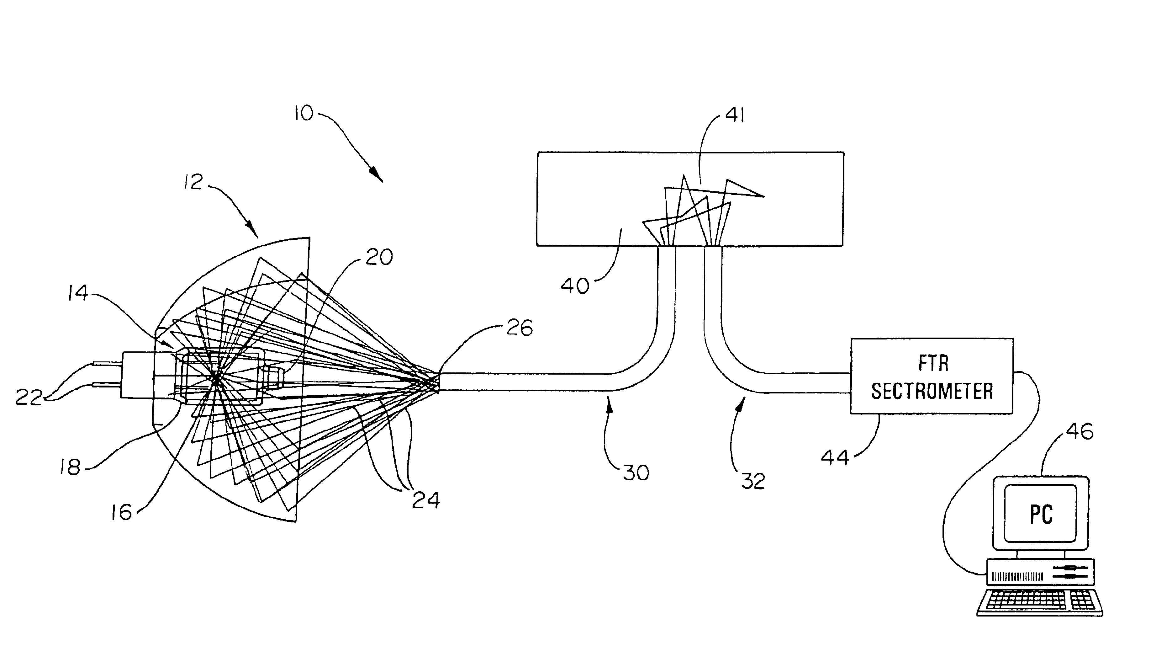
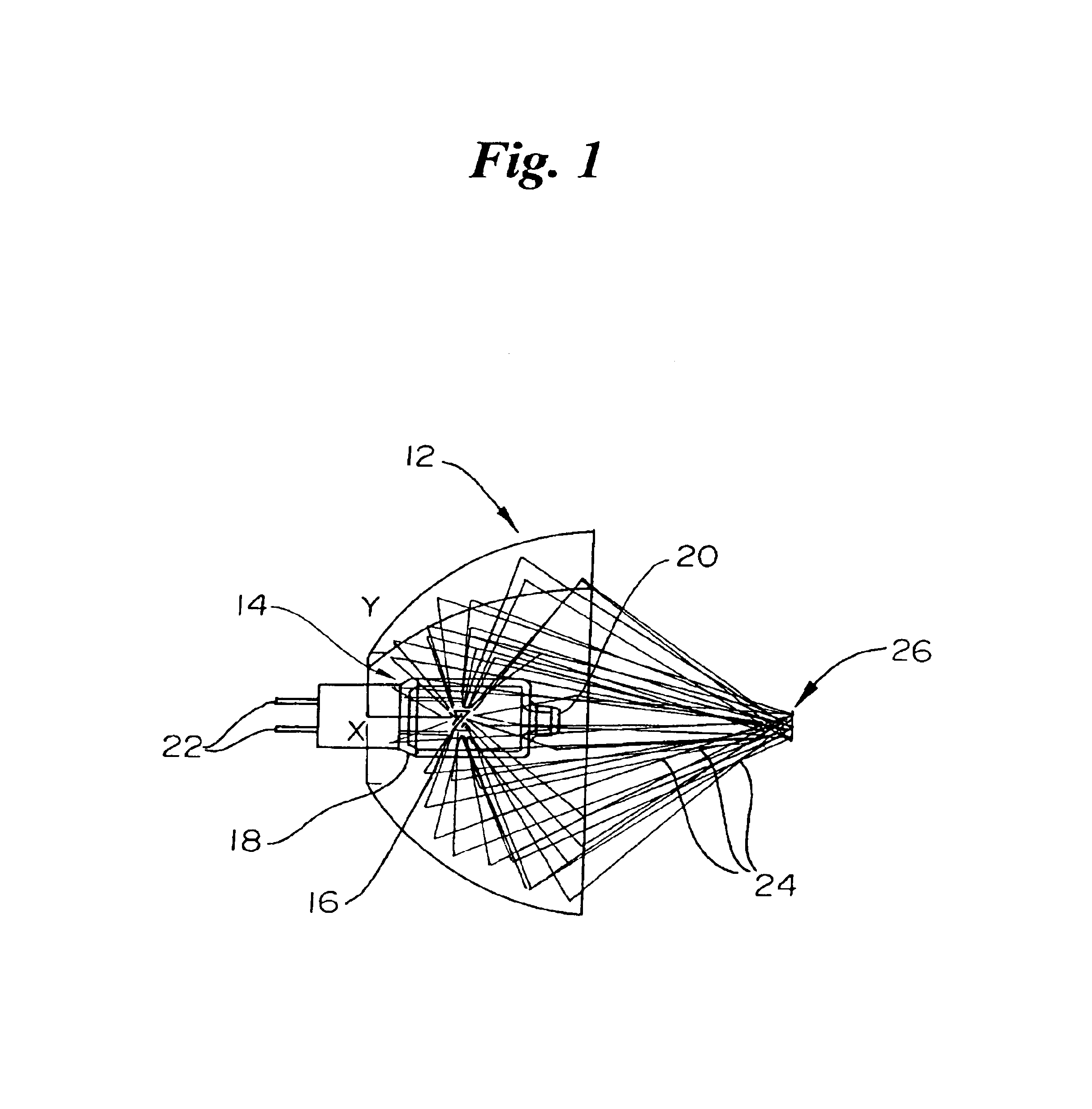
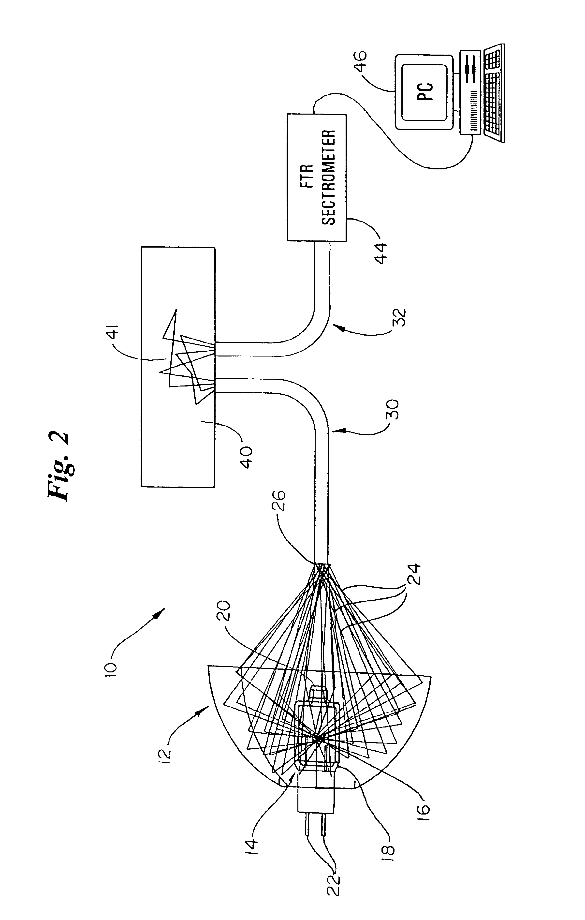
FIG. 1 shows a plan view of a near infrared radiation source lamp 14 known in the art. The appearance of a radiant source lamp 14 closely resembles that of a traditional residential light bulb. Traditional spectrophotometer lamps consist of a filament 16 housed within a transparent envelope 18, or the like. The transparent envelope 18 is either comprised of a silicate glass, fused silica or quartz material. The material used for the glass envelope 18 is dependent upo...


PUM


Abstract

An illumination subsystem for use in optical analysis which provides spatially and angularly homogenized radiation to the sample being analyzed. The system eliminates the illumination system as an interferent in the overall optical analysis. Thus, modest translations or rotations of the illumination source or changing the illumination source does not require recalibration of the instrument or prior modeling of illumination variability due to such changes. Illumination stability is achieved by incorporating a light pipe which both angularly and spatially homogenizes the light. Further, a series of filters and/or lenses are incorporated to provide bandpass filtering which eliminates unwanted wavelengths or bands of wavelengths from contacting the tissue and allows for a higher signal-to-noise ratio when the sample is tissue, while preventing thermal damage.

Description

TECHNICAL FIELDThe present invention generally relates to the field of diagnostic spectroscopy, and more specifically, to an improved illumination device for obtaining spectral information and determining physical properties of a tissue sample. The present invention provides for an illumination device including an element or elements that spatially and angularly homogenize radiation for illuminating a sample under analysis while maintaining a high signal-to-noise ratio.BACKGROUND OF THE INVENTIONSpectral data arising from spectroscopic analysis provides practitioners with a wealth of detailed information about the identity, structure, and concentration of samples or constituents of samples. Spectral data derives from the detected and recorded energy change of a molecule through the emission or absorption of a photon.In particular, practitioners focus upon a molecule's vibration. Atoms within a molecular species vibrate back and forth about an average distance. Absorption of light by...

Claims


Application Information

Patent Timeline
Patent Type & Authority Patents(United States)
IPC IPC(8): G01J3/02G01J3/00G02B27/00G01J3/10G02B6/42
CPCG01J3/02G01J3/0216G01J3/0218G02B27/0994G02B6/4298G02B27/0927G01J3/10G02B6/4206
Inventor JOHNSON, ROBERT D.
Owner RIO GRANDE MEDICAL TECH
Why Eureka
Try Eureka