Method for vapor phase aluminiding of a gas turbine blade partially masked with a masking enclosure

Active Publication Date: 2005-03-08
GEN ELECTRIC AVIATION SERVICE OPERATION PTE +1
View PDF10 Cites 18 Cited by
  • Summary
  • Abstract
  • Description
  • Claims
  • Application Information

AI Technical Summary

Benefits of technology

The top opening of the airfoil enclosure is desirably sized so that a top gap between the airfoil and the top opening is not greater than about 0.005 inch. Similarly, the bottom opening is desirably sized so that a bottom gap between the shank and the bottom opening is not greater than about 0.001 inch. This close fit between the openings and the respective portions of the turbine blade aids in preventing penetration of the aluminum-containing gas during the aluminiding step. Additionally, the top

Problems solved by technology

In current engines, the turbine vanes and blades are made of nickel-based superalloys, and can operate at temperatures of up to about 1800-2100° F. These components are subject to damage by oxidation and corrosive agents.
The application of the different types and thicknesses of protective coatings in some regions, and the prevention of coating depositio

Method used


Image

  • Method for vapor phase aluminiding of a gas turbine blade partially masked with a masking enclosure
  • Method for vapor phase aluminiding of a gas turbine blade partially masked with a masking enclosure
  • Method for vapor phase aluminiding of a gas turbine blade partially masked with a masking enclosure

Examples


Example

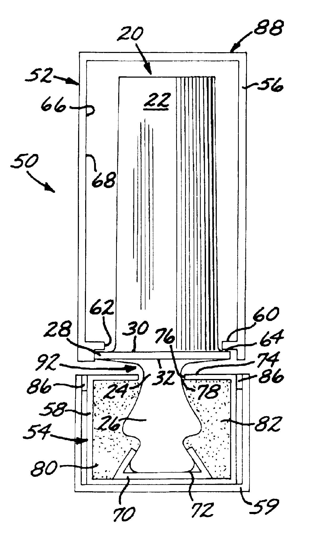
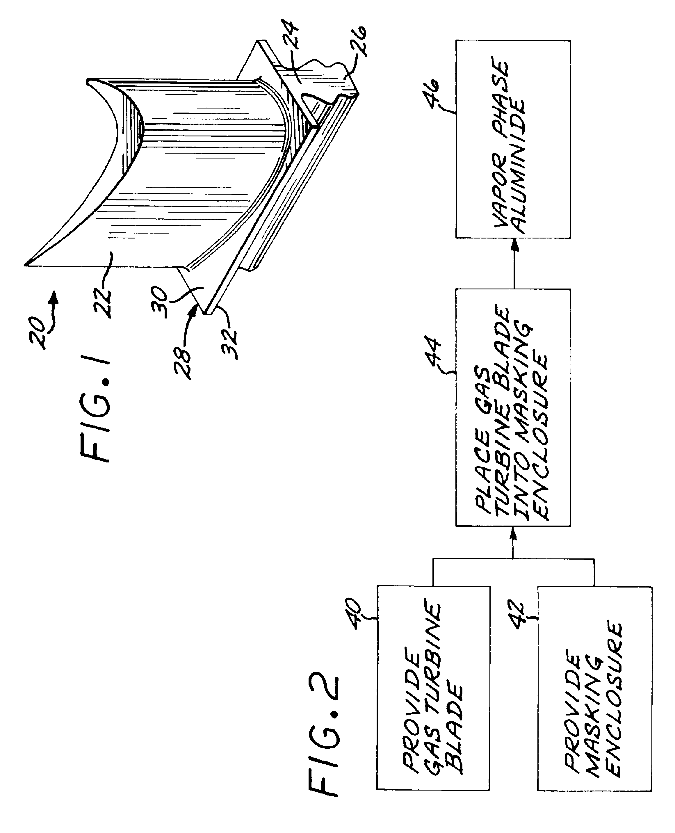
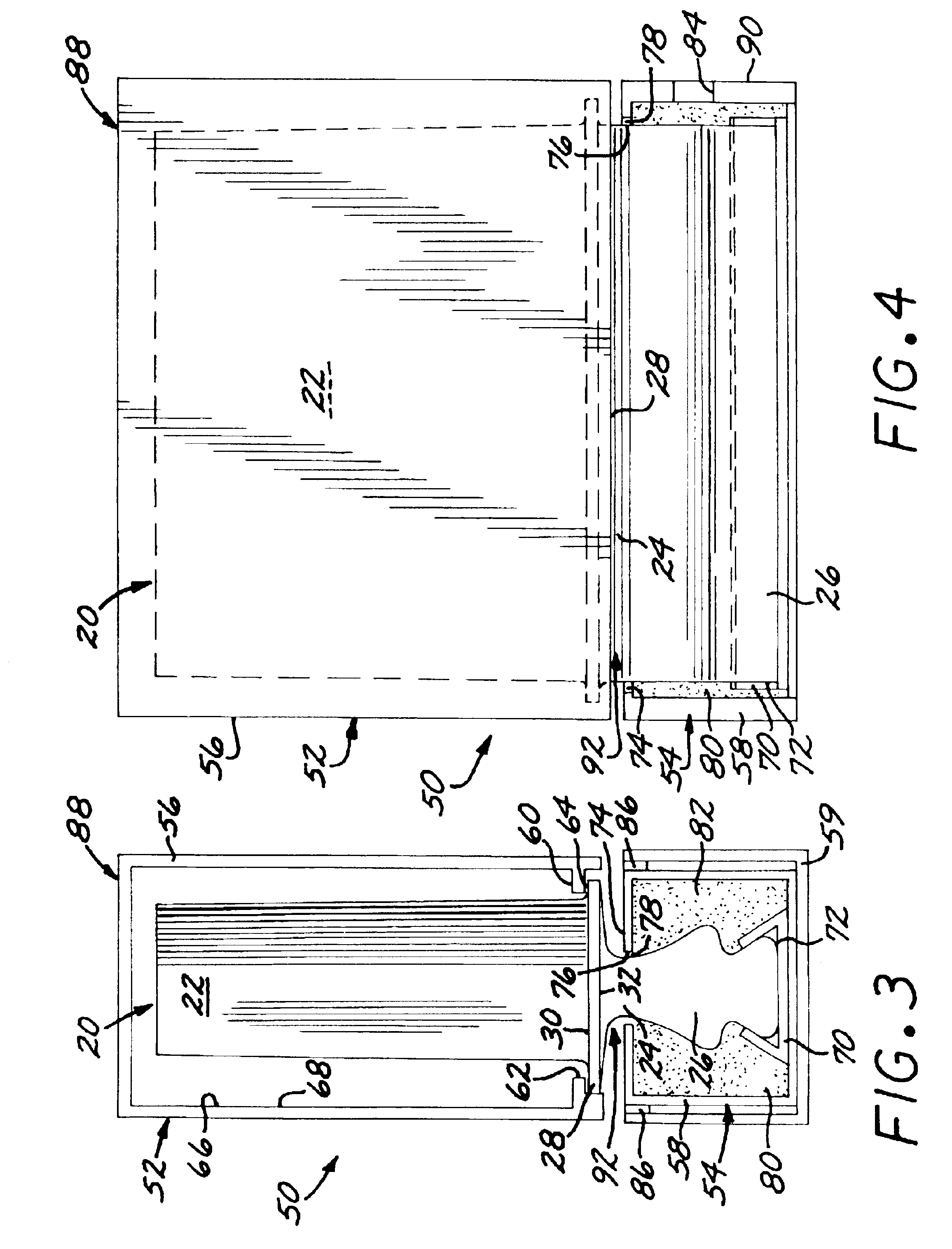
FIG. 1 depicts a gas turbine blade 20 which has preferably previously been in service, or which may be a new-make article. The gas turbine blade 20 has an airfoil 22 against which the flow of hot combustion gas impinges during service operation, a downwardly extending shank 24, and an attachment in the form of a dovetail 26 which attaches the gas turbine blade 20 to a gas turbine disk (not shown) of the gas turbine engine. A platform 28 extends transversely outwardly at a location between the airfoil 22 and the shank 24 and dovetail 26. The platform 28 has a top surface 30 adjacent to the airfoil 22, and a bottom surface 32 (sometimes termed an “underside” of the platform) adjacent to the shank 24 and the dovetail 26. An example of a gas turbine blade 20 with which the present approach may be used is the CF34-3B1 high pressure turbine blade, although the invention is not so limited.

The entire gas turbine blade 20 is preferably made of a nickel-base superalloy. A nickel-base alloy ha...


PUM

PropertyMeasurementUnit
Lengthaaaaaaaaaa
Lengthaaaaaaaaaa
Shapeaaaaaaaaaa

Abstract

A gas turbine blade to be protected by an aluminide coating is placed within a masking enclosure including an airfoil enclosure that prevents deposition on the airfoil of the gas turbine blade, and a dovetail enclosure that prevents deposition on the dovetail of the gas turbine blade. The assembly is vapor phase aluminided such that aluminum is deposited on an exposed portion of the gas turbine blade that is not within the masking enclosure.

Description

This invention relates to the gas turbine blades used in gas turbine engines and, more particularly, to selectively protecting portions of the gas turbine blades with a protective coating.BACKGROUND OF THE INVENTIONIn an aircraft gas turbine (jet) engine, air is drawn into the front of the engine, compressed by a shaft-mounted compressor, and mixed with fuel. The mixture is burned, and the hot combustion gases are passed through a turbine mounted on the same shaft. The flow of combustion gas turns the turbine by impingement against an airfoil section of the turbine blades and vanes, which turns the shaft and provides power to the compressor. The hot exhaust gases flow from the back of the engine, driving it and the aircraft forward.The hotter the combustion and exhaust gases, the more efficient is the operation of the jet engine. There is thus an incentive to raise the combustion and exhaust gas temperatures. The maximum temperature of the combustion gases is normally limited by the...

Claims


Application Information

Patent Timeline
IPC IPC(8): C23C10/00C23C10/04F01D5/28C23C14/14F02C7/00
CPCC23C10/04F01D5/288F01D5/28F05B2230/90F05D2230/90
Inventor LANGLEY, NIGEL BRIAN THOMASYOW, KWOK HENG
Owner GEN ELECTRIC AVIATION SERVICE OPERATION PTE
Why Eureka
Try Eureka