Apparatus of high power density fuel cell layer with micro for connecting to an external load

a fuel cell and micro-chip technology, applied in the field of fuel cells, can solve the problems of increasing the internal resistance of the stack, reducing the overall efficiency of the fuel cell, and difficulty in manufacturing the layers of existing fuel cell configurations, so as to simplify the manufacturing process and simplify the design

Inactive Publication Date: 2005-03-08
INTELLIGENT ENERGY LTD
View PDF13 Cites 29 Cited by
  • Summary
  • Abstract
  • Description
  • Claims
  • Application Information

AI Technical Summary

Benefits of technology

The present invention relates to a specific fuel cell layer architecture that is of an integrated design in which the functions of gas diffusion layers, catalyst layers, and electrolyte layers are integrated into a single substrate. This integrated design enables simpler manufacturing processes and scaling of the design.

Problems solved by technology

One major problem with the layered planar structure fuel cell has been that the layers must be held in intimate electrical contact with each other, which if intimate contact does not occur the internal resistance of the stack increases, which decreases the overall efficiency of the fuel cell.
A second problem with the layered planar structured fuel cell has been to maintain consistent contact between the layers for sealing and ensuring correct flows of reactants and coolants in the inner recesses of the layer structured fuel cell.
Also if the overall area of the cell becomes too large then there are difficulties creating the contacting forces needed to maintain the correct fluid flow distribution of reactant gases over the electrolyte surface.
As a result, both sealing and conductivity require the assembled stack to be clamped together with significant force in order to activate perimeter seals and reduce internal contact resistance.
The manufacture of the layers for existing fuel cell configurations is often expensive and difficult.
The bipolar plates, which serve as oxidant and fuel flowfields as well as the separator are often constructed from graphite which is difficult to machine, adding significant cost to the fuel cell stack.
Complex bipolar plates that are difficult to manufacture provide both fuel and oxidants to both sides of the MEA layer.
Such perimeter electrical connections are inefficient.
However, this design still relies on the expensive and complicated layered structure with explicit seals and requires compressive force to maintain internal electrical contact and sealing.
As with GB 2,339,058, this document continues to rely on the expensive and complicated layered structure but this design also puts undue stress on the MEA by forcing it into a non-planar arrangement using the separator plates.

Method used


Image

  • Apparatus of high power density fuel cell layer with micro for connecting to an external load
  • Apparatus of high power density fuel cell layer with micro for connecting to an external load
  • Apparatus of high power density fuel cell layer with micro for connecting to an external load

Examples


Embodiment Construction

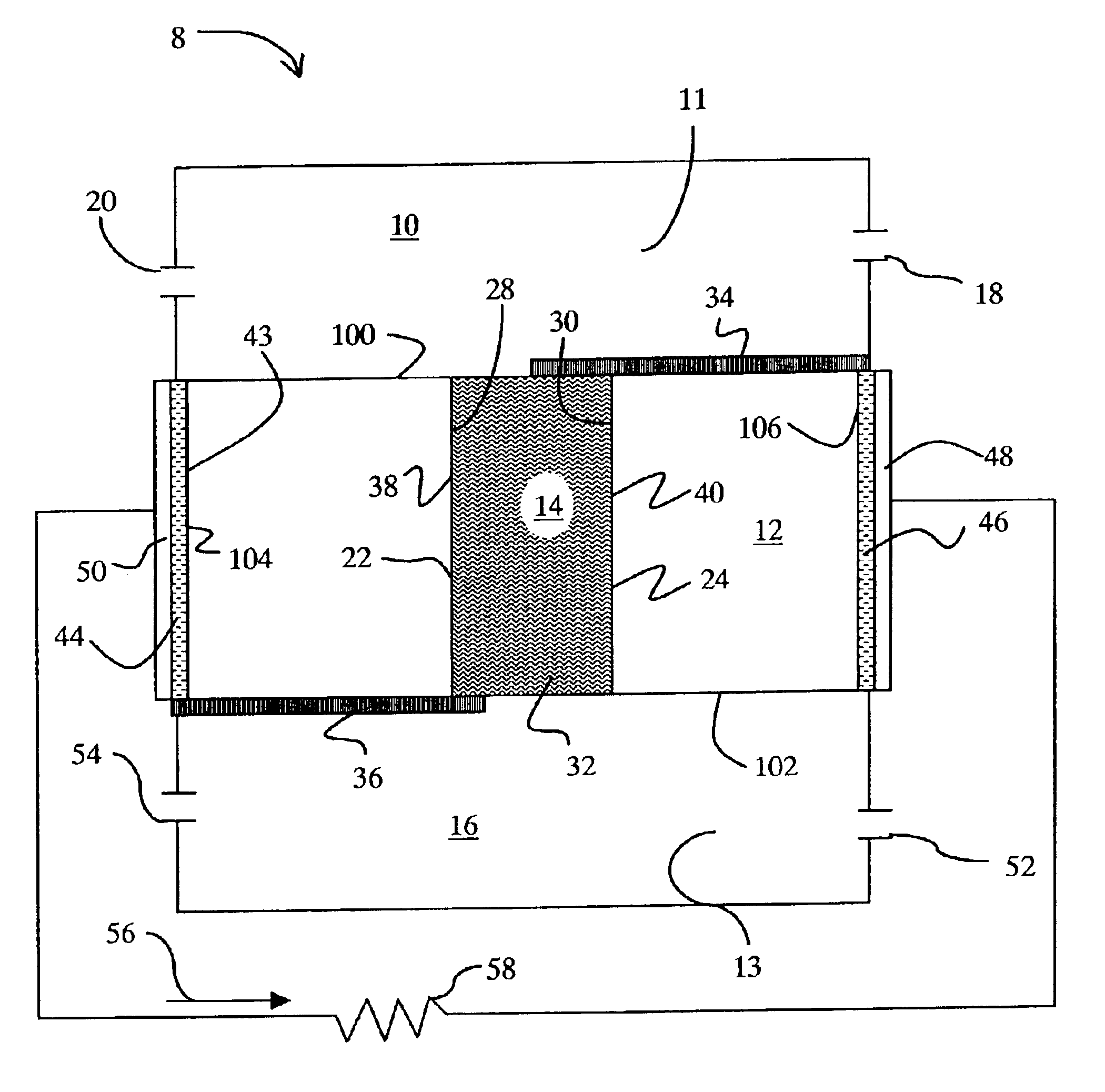
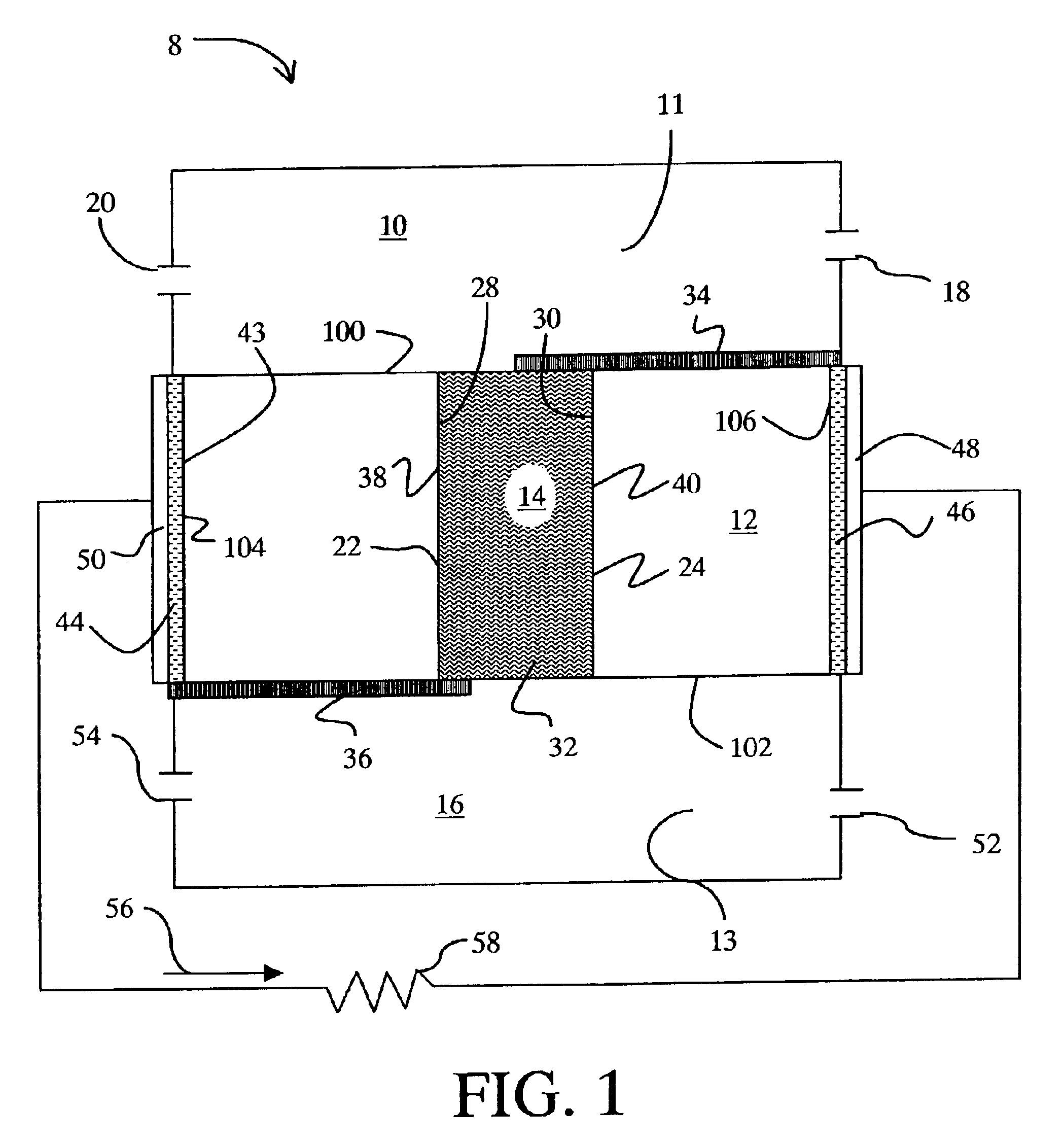
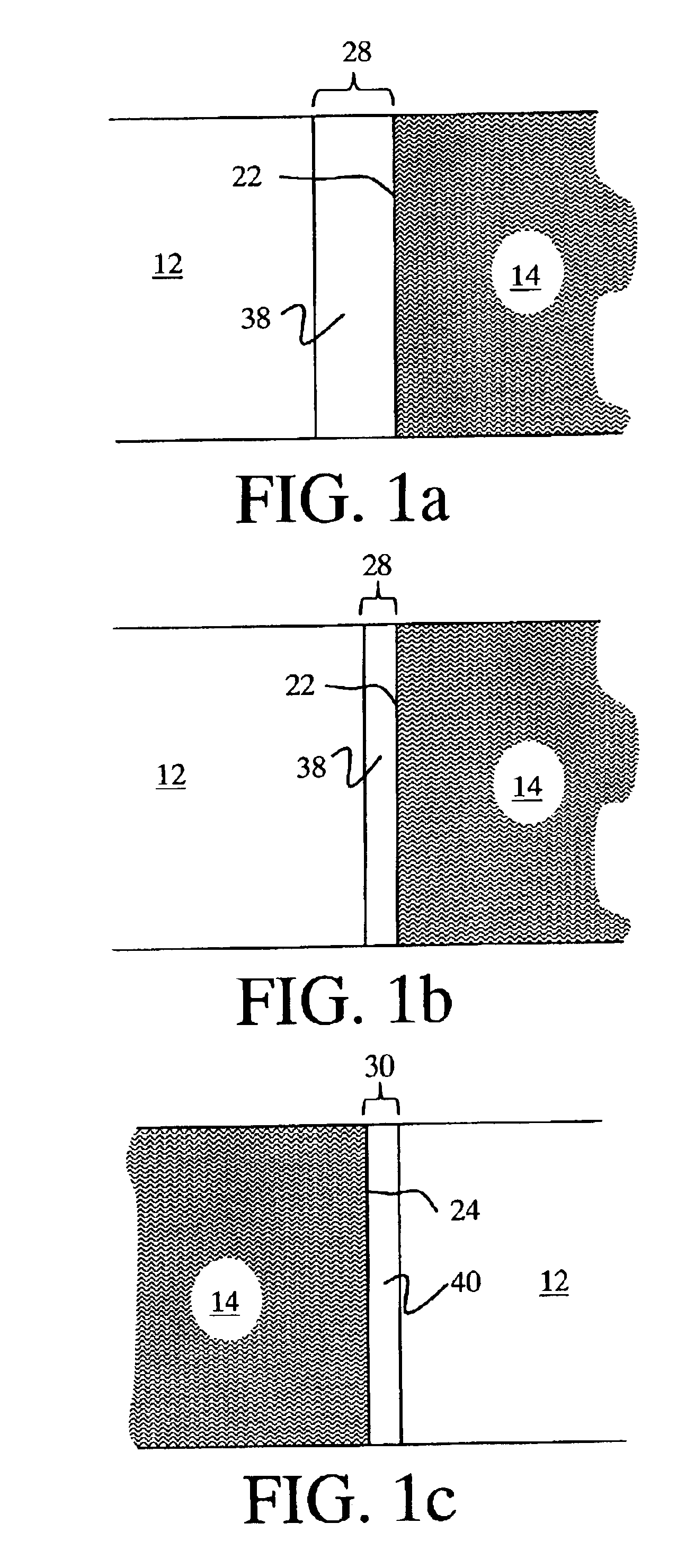
The present invention relates to a microstructure fuel cell having a substrate, which is preferably porous, an assembly of fuel cells having a single or multiple substrate structure and methods for manufacturing such fuel cells and fuel cell layers.

The invention relates to a specific fuel cell architecture that is of an integrated design in which the functions of gas diffusion layers, catalyst layers, and electrolyte layers are integrated into a single substrate. This architecture makes it possible to fold together the various ‘layers’ of which a working fuel cell is formed and produce linear, curvilinear, undulating or even fractal shaped electrolyte paths that allow for higher volumetric power density to be achieved by increasing the electrochemically active surface area. In addition, by forming the various fuel cell layers within a single substrate the problem of simple contacting of fuel cell components to create electrical connections is eliminated, thus creating the potential ...


PUM

PropertyMeasurementUnit
widthaaaaaaaaaa
heightaaaaaaaaaa
heightaaaaaaaaaa

Abstract

The invention is a fuel cell layer for connecting to an external load made of a fuel plenum, an oxidant plenum, a porous substrate connecting the fuel and oxidant plenums, and a plurality of fuel cells, wherein each cell has a distinct channel, two catalyst layers, an anode in one layer and a cathode in the other layer, an electrolyte in the channel to prevent transfer of fuel to the cathode and oxidant to the anode, two coatings on the porous substrate to prevent fuel or oxidant, sealant barriers, and a positive electrical and negative electrical connection disposed on the side of the channel.

Description

FIELD OF THE INVENTIONThe present invention relates to fuel cells. More specifically the invention relates to a fuel cell layer comprising multiple cells within distinct channels formed using a single porous substrate.BACKGROUND OF THE INVENTIONHigh power density fuel cells have long been desired.Existing fuel cells generally are a stacked assembly of individual fuel cells, with each cell producing high current at low voltage. The typical cell construction involves reactant distribution and current collection devices brought into contact with a layered electrochemical assembly consisting of a gas diffusion layer, a first catalyst layer, an electrolyte layer, a second catalyst layer and a second gas diffusion layer. With the exception of high temperature fuel cells, such as molten carbonate cells, most proton exchange membrane, direct methanol, solid oxide or alkaline fuel cells have a layered planar structure where the layers are first formed as distinct components and then assemble...

Claims


Application Information

Patent Timeline
Patent Type & Authority Patents(United States)
IPC IPC(8): H01M8/04
CPCH01M8/1004H01M8/241H01M8/04089H01M8/0271Y02E60/521H01M8/0258H01M8/2457Y02E60/50
Inventor MCLEAN, GERARD FRANCIS
Owner INTELLIGENT ENERGY LTD
Why Eureka
Try Eureka