Difluoromethyl ether derivative and process for producing the same

a technology of difluoromethyl ether and ether derivative, which is applied in the field of difluoromethyl ether derivative, can solve the problems of unsatisfactory yield and the process is not necessarily simple and efficient for producing difluoromethyl ether derivative, and achieves simple and efficient process, high yield, and high yield

Inactive Publication Date: 2005-03-08
JNC CORP
View PDF6 Cites 12 Cited by
  • Summary
  • Abstract
  • Description
  • Claims
  • Application Information

AI Technical Summary

Benefits of technology

An object of the present invention is to provide a process for producing a difluoromethyl ether derivative which shows various suitable physical properties as a liquid crystal compound, a liquid crystal composition comprising the compound and a liquid crystal display element containing the liquid crystal composition, and to provide a simple and efficient process for producing the above difluoromethyl ether derivative.
The present inventors have made intensive investigations in order to achieve the above object and, as a result, found that the intended difluoromethyl ether derivative can be obtained in a high yield by adding halogen to an α,α-difluorocyclohexylidene derivative or a difluorovinyl derivative as an intermediate, reacting with a phenol derivative, and then reducing it with hydrogen. Further, the inventors have found that when adding hydrogen halide to the difluorovinyl derivative, a halogen atom is quantitatively added onto a difluoromethyl carbon and that it is then reacted with a phenol derivative, whereby the intended difluoromethyl ether derivative can be obtained in a high yield. In addition, the inventors have found that the compound represented by Formula (1c′) having a 1,1-difluoro-2-propenyloxy group as a bonding group, which is obtained as an intermediate in the process of the present invention, has excellent characteristics as a liquid crystal material, and thus completed the present invention.

Problems solved by technology

In the process described above, however, the thioesterification reaction with a Lawesson's reagent results in unsatisfactory yield.
HF-Pyridine is strongly corrosive and requires a specific facility in handling in the fluorination reaction, so that the process is not necessarily simple and efficient for producing a difluoromethyl ether derivative.

Method used


Image

  • Difluoromethyl ether derivative and process for producing the same
  • Difluoromethyl ether derivative and process for producing the same
  • Difluoromethyl ether derivative and process for producing the same

Examples


example 1

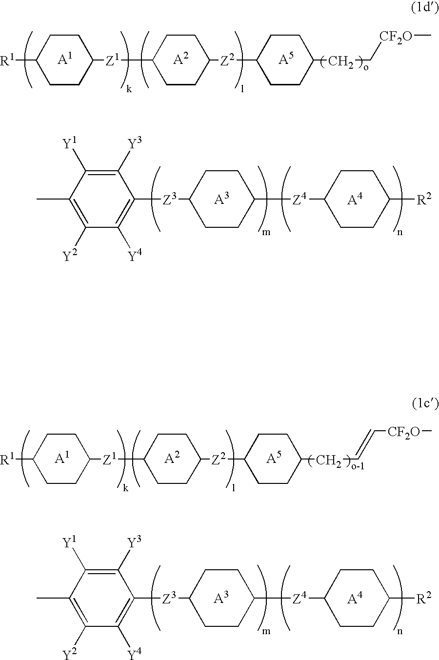
Production of 1-(trans-4-(trans-4-propylcyclohexyl)cyclohexyldifluoromethoxy)-3,4,5-trifluorobenzene (the compound (1d), wherein k is 1, and l, m and n are 0; R1 is n-propyl; ring A1 is trans-1,4-cyclohexylene; Z1 is a single bond; both Y1 and Y2 are hydrogen; and all of Y3, Y4 and R2 are fluorine (Compound No. 17))

Production of Starting Material, Compound (1a)

In a nitrogen-purged 1-L three-neck flask equipped with a stirrer, a thermometer and a dropping funnel, 49.7 g (0.23 mol) of dibromodifluoromethane was dissolved in 100 ml of THF and the solution was cooled down to −20° C. while stirring. 117 g (0.47 mol) of tris(diethylamino)phosphine dissolved in 200 ml of THF was added dropwise at 10° C. or lower, and then the solution was stirred at room temperature for one hour. Next, 35 g (0.16 mol) of 4-(trans-4-propylcyclohexyl)cyclohexanone dissolved in 100 ml of THF was added dropwise at 30° C. or lower, and then the solution was stirred at room temperature for 6 hours. The reaction ...

example 2

Production of 1-(trans-4-(trans-4-pentylcyclohexyl)cyclohexyldifluoromethoxy)-4-trifluoromethoxybenzene (a compound (1d), wherein k is 1, and l, m and n are 0; R1 is n-pentyl; ring A1 is trans-1,4-cyclohexylene; Z1 is a single bond; all of Y1, Y2, Y3 and Y4 are hydrogen; and R2 is trifluoromethoxy (Compound No. 18))

First Step

A nitrogen-purged 100-ml three-neck flask equipped with a stirrer, a thermometer and a condenser was charged with 8.0 g (28.1 mmol) of 4-(trans-4-pentylcyclohexyl)-α,α-difluorocyclohexylidene obtained by the same method of preparing the compound (1a) in Example 1 and 24.2 g (140.7 mmol) of 47% hydrobromic acid, and the solution was heated under reflux for 5 hours. The reaction mixture was transferred into a 1-L beaker, and 150 ml of water and 200 ml of heptane were added thereto. The separated heptane layer was washed three times with 150 ml of water and dried over anhydrous magnesium sulfate. The solvent was distilled off under reduced pressure, and then the co...

example 3

Production of 1-(3-(trans-4-(trans-4-pentylcyclohexyl)cyclohexyl)-1,1-difluoro-2-propenyloxy)-3,4,5-trifluorobenzene (a compound (1c′), wherein k is 1; l, m and n are 0; o is 1; R1 is n-pentyl; both ring A1 and ring A5 are trans-1,4-cyclohexylene; Z1 is a single bond; both Y1 and Y2 are hydrogen; and all of Y3, Y4 and R2 are fluorine (Compound No. 105))

Production of Starting Material, Compound (1a′)

A nitrogen-purged 1-L three-neck flask equipped with a stirrer, a thermometer and a dropping funnel was charged with 16.4 g (107.7 mmol) of sodium chlorodifluoroacetate, 28.3 g (107.7 mmol) of triphenylphosphine and 200 ml of DMF, and the mixture was heated up to 80° C. while stirring. A solution of 15.0 g (53.9 mmol) of 1-(trans-4-(trans-4-pentylcyclohexyl)cyclohexyl)acetaldehyde dissolved in 100 ml of DMF was added dropwise at 80 to 110° C., and the solution was stirred at 100° C. for 2 hours. The reaction mixture was transferred into a 2-L beaker, and 500 ml of heptane was added theret...


PUM

PropertyMeasurementUnit
optical anisotropyaaaaaaaaaa
dielectric anisotropyaaaaaaaaaa
threshold voltageaaaaaaaaaa

Abstract

The present invention provides a process for producing a difluoromethyl ether derivative simple and efficient process for producing the difluoromethyl ether derivative represented by Formula (1d′) or a difluoromethyl ether derivative represented by Formula (1c′): wherein all the variables are defined in the specification.

Description

FIELD OF THE INVENTIONThe present invention relates to a difluoromethyl ether derivative which is useful as a liquid crystalline compound, a liquid crystal composition comprising the compound and a liquid crystal display element using the composition. Further, the present invention relates to a simple and efficient process for producing the difluoromethyl ether derivative.BACKGROUND OF THE INVENTIONA liquid crystal display element makes use of optical anisotropy and dielectric anisotropy of a liquid crystal crystalline compound and is used for watches, electric calculators, various measuring instruments, panels for automobiles, word processors, electronic notebooks, printers, personal computers, televisions and portable telephones. There has been an increasing demand therefor year by year. A liquid crystal phase is between a solid phase and a liquid phase, and divided roughly into a nematic phase, a smectic phase and a cholesteric phase. Display elements making use of a nematic phas...

Claims


Application Information

Patent Timeline
Patent Type & Authority Patents(United States)
IPC IPC(8): C09K19/20C09K19/42C09K19/10C09K19/34C09K19/30G02F1/13C07B61/00C07C41/20C07C43/225C07C253/30C07C255/54C07D239/26C07D239/34C07D309/06C07D319/06C07D335/02C07D339/08C09K19/12C09K19/14
CPCC09K19/20C09K19/3066C09K19/3402C09K19/3458C09K19/3491C09K19/42C09K19/3469Y10T428/10C09K2019/0466C09K2019/3422C09K2323/00
Inventor KONDO, TOMOYUKISAGOU, KOUKIMATSUI, SHUICHITAKEUCHI, HIROYUKIKUBO, YASUHIRONAKAGAWA, ETSUO
Owner JNC CORP
Why Eureka
Try Eureka