Friction stir welding method

Inactive Publication Date: 2005-03-15
HITACHI LTD
View PDF18 Cites 47 Cited by
  • Summary
  • Abstract
  • Description
  • Claims
  • Application Information

AI Technical Summary

Benefits of technology

According to the invention, in friction stir welding, in which a welding tool is used, resistance heating is caused on the welding tool by flowing

Problems solved by technology

Preferably, however, a coating layer of a heater should be provided on surfaces

Method used


Image

  • Friction stir welding method
  • Friction stir welding method
  • Friction stir welding method

Examples


embodiment 1

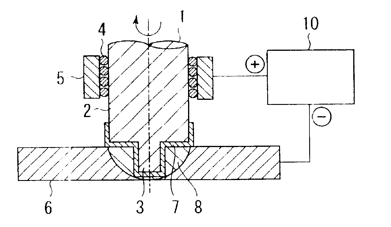
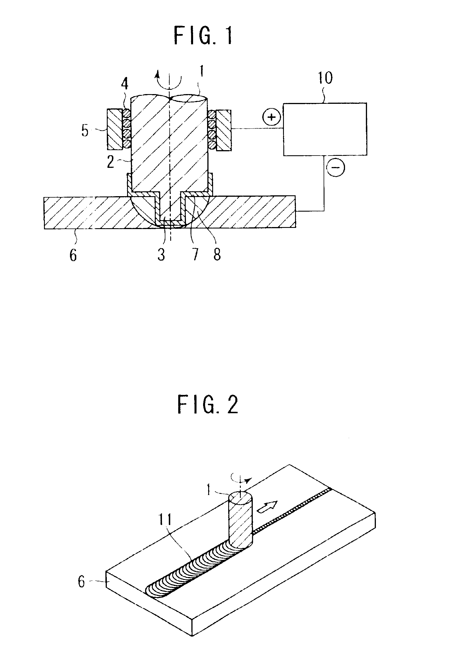
FIG. 1 is a cross sectional view showing a state, in which a welding tool is plugged into a welding zone of workpieces. FIG. 2 is a perspective view. However, illustration of a power supply device is omitted. A welding tool 1 comprises a large-diameter shoulder 2 and a small-diameter pin 3. The welding tool 1 is press-fitted into workpieces 6 while rotating. In this state, welding is performed by moving the welding tool 1 in a welding direction as shown in FIG. 2. The welding tool 1 is held by a bearing 4 and a spindle wall 5. Also, a power supply device 10 allows a current to flow between the spindle wall 5 and the workpieces 6.

Rotation of the welding tool 1 causes metal flow of the workpieces 6 to form a metal flow zone 8. The metal flow zone 8 may be considered to correspond to a stir zone 11 shown in FIG. 2.

A conductive ceramic 7 is coated on that surface portion of the welding tool 1, which contacts with the workpieces 6. When the power supply device 10 allows a current to flow...

embodiment 2

In FIG. 5, only surfaces of the pin 3 on the welding tool 1 are coated with the conductive ceramic 7, and surfaces of the shoulder 2 are coated with an insulating ceramic 21. It is desired that Sialon, Silicon Nitride (Si3N4), or the like be used for the insulating ceramic 21. Also, the insulating ceramic may be the same in thickness and coating method as the conductive ceramic. In the embodiment, heat can be selectively generated only on surfaces of the pin 3 because the insulating ceramic 21 generates no heat. Generally, resistance heating is desirably generated on the pin 3 from a point of view that temperature should be prevented from rising excessively near the shoulder 2 because friction heat is generated in a higher ratio on the surfaces of the shoulder 2 than on the surfaces of the pin 3 due to a large peripheral speed of the shoulder.

embodiment 3

FIG. 6 shows an embodiment, in which the insulating ceramic 21 is coated on the surfaces of the shoulder 2 and a surface of a root of the pin 3 and the conductive ceramic 7 is coated on a tip end of the pin so that only the tip end of the pin 3 causes resistance heating. According to the embodiment, it is possible to control a temperature distribution in the metal flow zone 8. While a calorific value is much generated on the surfaces of the shoulder 2, which are largest in peripheral speed, in the conventional method and so temperature becomes too high in some cases, resistance heating is caused only at the tip end of the pin 3 in the embodiment, so that the metal flow zone 8 is made uniform in temperature to enable welding with no defect even when the welding speed is increased.


PUM

PropertyMeasurementUnit
Forceaaaaaaaaaa
Electrical conductivityaaaaaaaaaa
Diameteraaaaaaaaaa

Abstract

There is provided a method capable of decreasing a friction force in friction stir welding, in which a welding tool is used. In a method of friction stir welding workpieces together by rotating and pressingly plugging a welding tool, formed from a harder material than the workpieces, into a weld zone of the workpieces and moving the welding tool relatively in a welding direction, a power supply device allows a current to flow between the welding tool 1 and the workpieces to cause resistance heating of the welding tool. Combined use of resistance heating makes it possible to decrease a friction force. Preferably, a conductive ceramic is coated on surfaces of the welding tool to cause resistance heating.

Description

BACKGROUND OF THE INVENTIONThe present invention relates to a method of plugging a rotating welding tool into a weld zone of workpieces to perform friction stir welding, and a friction stir welding apparatus.Methods of solid-state welding two workpieces without melting include a welding method making use of a friction stir phenomenon caused by rotation of a welding tool, formed from a harder material than the workpieces, by rotating and plugging the welding tool into a weld zone of the workpieces and moving the welding tool along a welding direction, such method being called friction stir welding.Included among friction stir welding is one, in which an external heat source such as laser or the like preheats a weld zone and its neighborhood (for example, see Patent Document 1).Patent Document 1: JP-A-10-225781 (Abstract, claim 1, FIG. 1)In the case where temperature of a weld zone is raised only by friction heat generated between a welding tool and workpieces in friction stir welding...

Claims


Application Information

Patent Timeline
IPC IPC(8): B23K20/12H05B7/00
CPCB23K20/1255B23K20/122
Inventor AOTA, KINYAOKAMURA, HISANORISATO, KOUJI
Owner HITACHI LTD
Why Eureka
Try Eureka