Noise suppression system and method for phased-array based systems

a phasedarray and suppression system technology, applied in the field of phased-array based systems, can solve the problems of reducing radar data complexity, affecting the detection process, and avoiding azimuthal degradation, so as to avoid the effect of azimuthal degradation

Active Publication Date: 2005-03-15
RAYTHEON CANADA LTD
View PDF6 Cites 42 Cited by
  • Summary
  • Abstract
  • Description
  • Claims
  • Application Information

AI Technical Summary

Benefits of technology

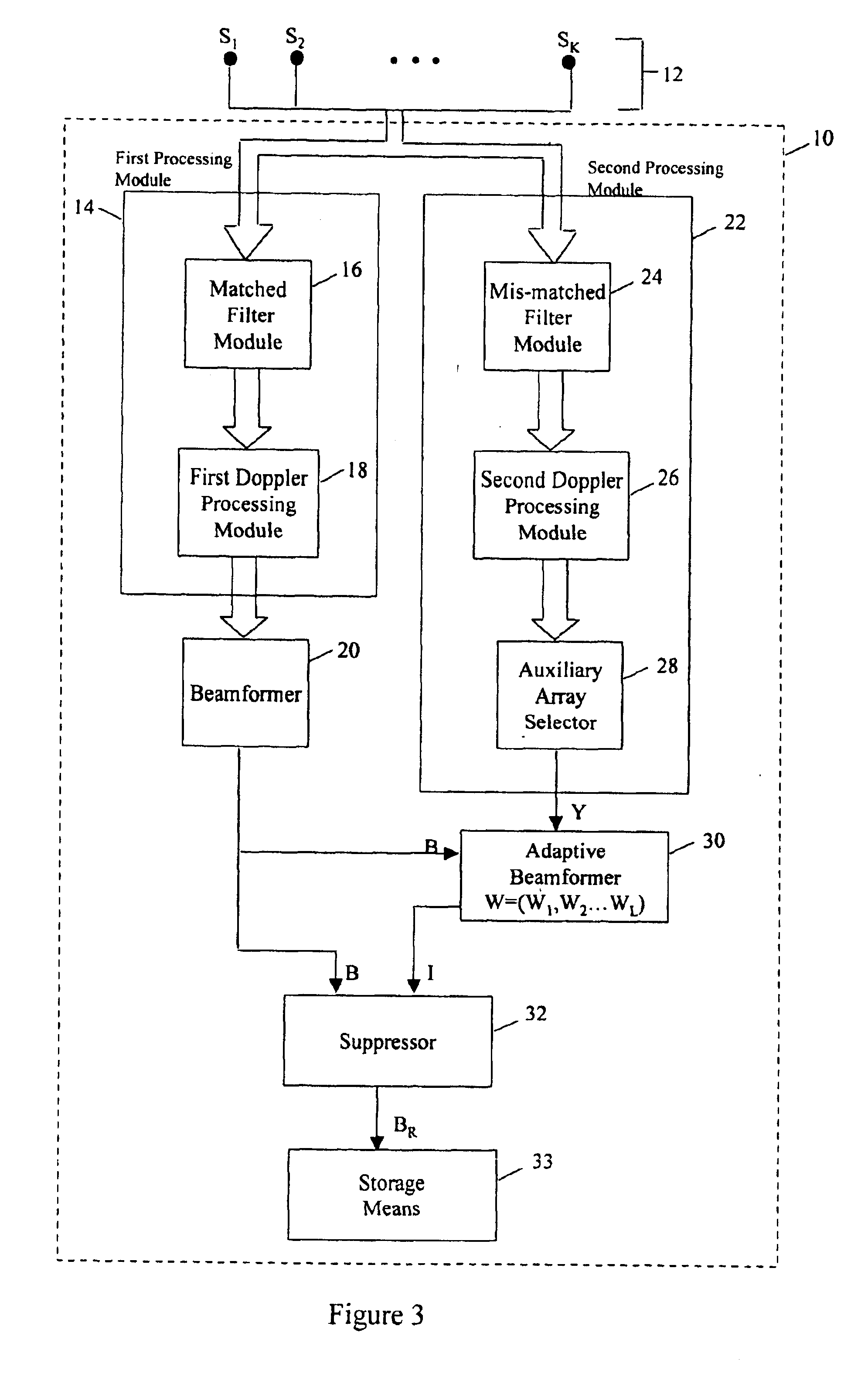
The matched radar data is tuned to a desired azimuth by using beamforming, as is commonly known in the art, in effect producing a main beam directed along a desired azimuth. The mis-matched radar data allows for the construction of a virtual auxiliary sensor array, with sensors selected from the main sensor array, to adaptively form an auxiliary beam. The auxiliary beam is tuned such that the external interference in the auxiliary beam provides an estimate of the external interference in the main beam. The adaptive beamforming involves generating an adaptive weight vector according preferably to Wiener theory to tune the auxiliary beam. The adaptive weight vector is chosen such that the error between the estimate of external interference provided by the auxiliary beam and the external interference in the main beam is minimized in a mean square error sense.
The virtual auxiliary sensor array may comprise either all the sensors of the main sensor array or a subset of the sensors from the main sensor array. In both cases, none of the sensors from the main sensor array are sacrificed to only produce an estimate of the external interference thus avoiding azimuthal degradation. Furthermore, the extra hardware of a physically separate auxiliary array is also avoided.

Problems solved by technology

Accordingly, the downsampled radar data is also complex and each of the signal processing components required to perform the above-mentioned operations are implemented to handle complex data.
The detection process is hindered by the addition of noise, which includes the clutter previously mentioned, in each cell which may result in the missed detection of a target or the false detection of noise as a target.
The noise is problematic since there will be a varying noise level in different cells as well as for radar data collected in different CITs, in different sea-state conditions, during different times of day and season and at different locations.
The major sources of radar noise include self-interference, such as ocean clutter, ionospheric clutter and meteoroid clutter, and external interference such as co-channel interference, atmospheric interference and impulsive noise.
Self-interference results from the operation of the radar while external interference is independent of radar operation.
Ionospheric clutter is one of the most significant causes of interference and is difficult to suppress due to its target-like nature and high signal amplitude.
However, this approach may decrease the performance of the radar system in detecting ships at long range due to the greater propagation loss that is incurred at higher transmission frequencies.
However, there is also higher order scatter, related to the sea-state, that results in additional peaks and a continuum of ocean clutter between the Bragg lines.
This continuum of ocean clutter contains energy that is related to the sea-state (i.e. surface wind speed and duration) often limits the detection of small, low-speed targets such as ships.
Meteoroid clutter results in an increase of the background noise level in range-doppler plots.
Co-channel interference results from both local and distant users of the HFSWR frequency band, such as television broadcasters.
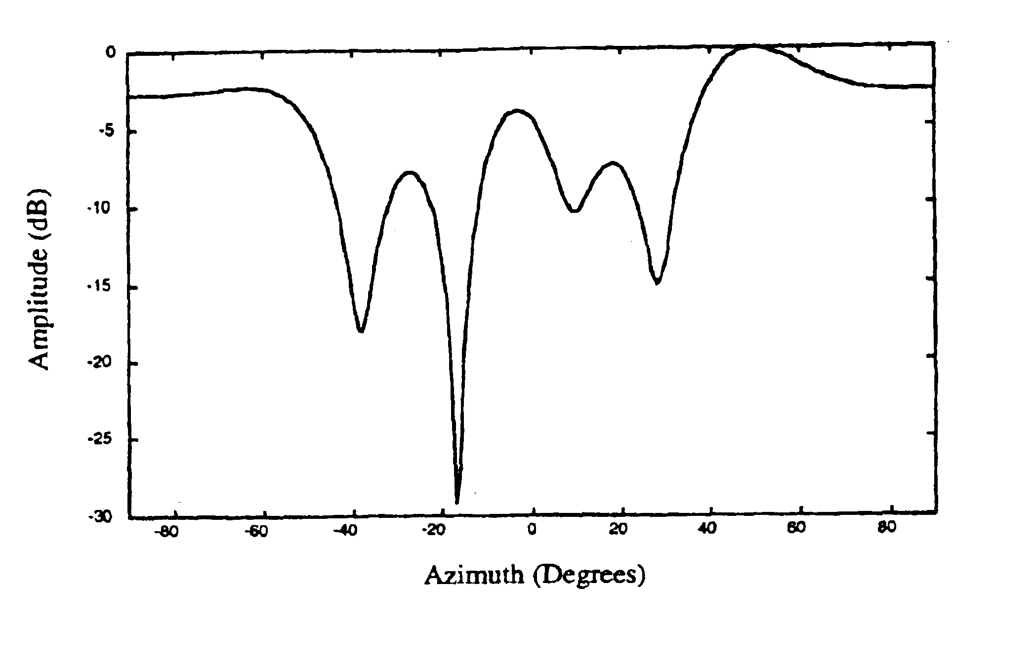
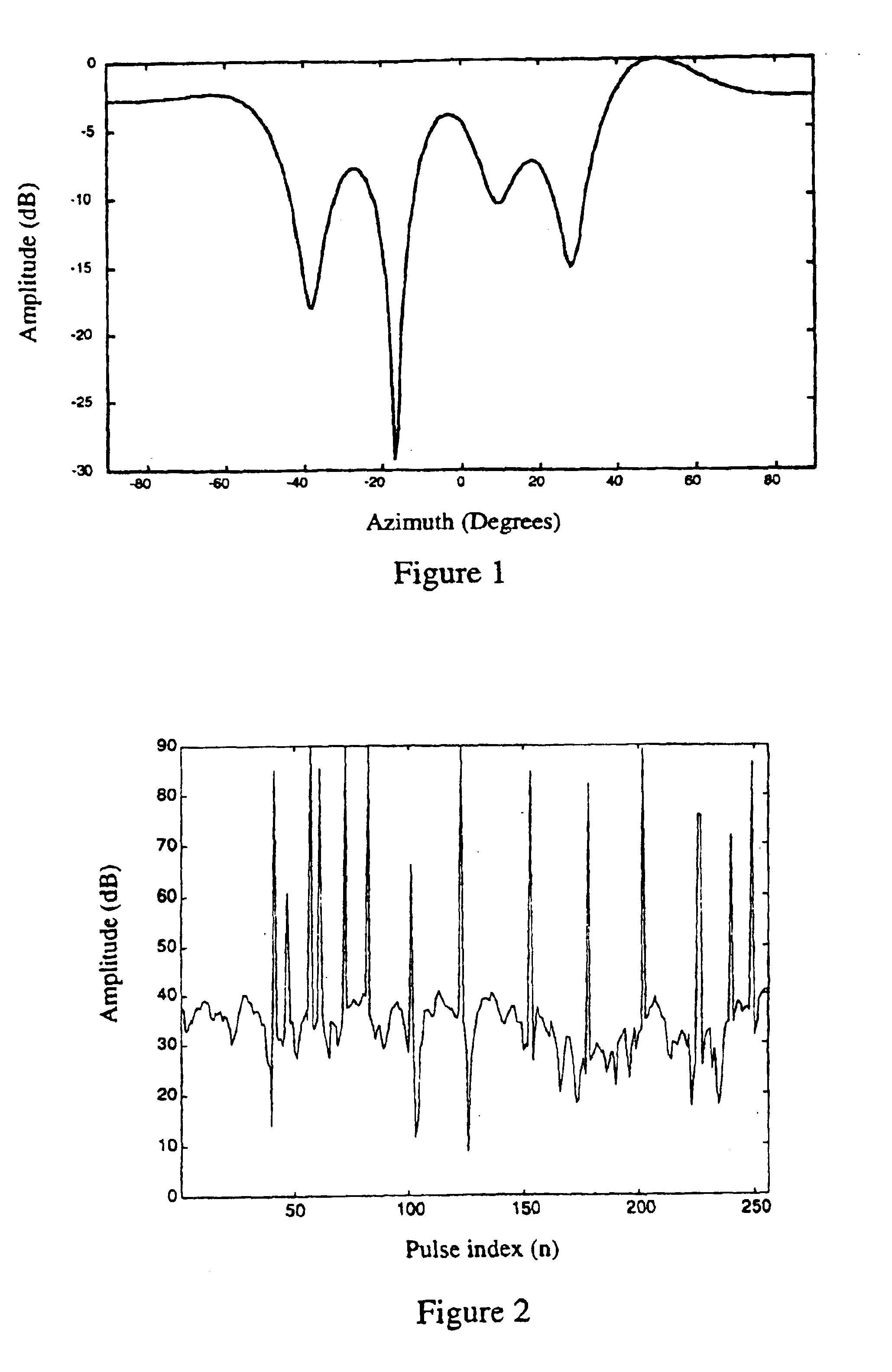
However, due to multiple reflections in non-uniform ionospheric layers, the direction of arrival of co-channel interference is wide as can be seen from a sample of real radar data shown in FIG.
However, co-channel interference from distant sources poses a more serious problem since this interference is more random in time and frequency.
Furthermore, there is typically greater co-channel interference at night than during the day due to the lack of D layer absorption during the night.
Impulsive noise usually occurs throughout the daily operation of an HFSWR system.
Impulsive noise results in an increase in the background noise level.
However, after applying these signal processing methods, the range-doppler-azimuth data still contains external interference comprised mainly of co-channel interference and impulsive interference.
However, these methods require the additional hardware of an auxiliary antenna or an auxiliary antenna array.
However, this results in a main antenna array having a smaller aperture (i.e. a smaller number of antenna elements) which degrades azimuthal resolution.

Method used


Image

  • Noise suppression system and method for phased-array based systems
  • Noise suppression system and method for phased-array based systems
  • Noise suppression system and method for phased-array based systems

Examples


Embodiment Construction

All of the experimental data shown herein has been taken from the SWR-503™ HFSWR system located at Cape Race, Newfoundland, Canada. The SWR-503™ HFSWR system was developed by Raytheon Canada Limited. The SWR-503 HFSWR system comprises a receiving antenna array having 16 antenna elements (i.e. a main sensor array having 16 sensors).

As used herein, each of the terms “range data”, “doppler data”, “azimuth data”, “sensor data” or “pulse data” denotes a one-dimensional series of data points in a given domain. Furthermore, the term “range-doppler data” denotes two-dimensional data for a given azimuth or for a given sensor and the term “range-sensor data” denotes two-dimensional data for a given doppler value or a given pulse index. In addition, the terms “range-pulse-sensor”, “range-doppler-sensor” and “range-doppler-azimuth data” denotes three-dimensional data. Furthermore, the term “a portion” of data means that the portion of data has a dimension smaller than the data from which it was...


PUM


Abstract

This invention relates to a system and method for suppressing external interference in radar data provided by a plurality of sensors from a main sensor array, the data being pre-processed. The noise suppression system includes a first processing module and a second processing module. The first processing module receives the radar data and produces matched radar data while the second processing module receives the radar data and produces mis-matched radar data. The system further includes a beamformer that is in communication with the first processing module and an adaptive beamformer that is in communication with the second processing module and the beamformer. The beamformer receives the matched radar data and produces beamformed matched radar data.

Description

FIELD OF THE INVENTIONThe present invention relates to noise reduction in phased-array systems, and more particularly, to a system and method for noise reduction in phased-array systems using adaptive array processing.BACKGROUND OF THE INVENTIONHigh Frequency Surface Wave Radar (HFSWR) is effective for the continuous detection and tracking of ships, aircraft, icebergs and other surface targets from a shore based location. Accordingly, HFSWR is being used to enhance search and rescue activities as well as to monitor sea state, illegal immigration, drug trafficking, illegal fishing, smuggling and piracy.An HFSWR system is installed along a coastal line and includes a directional transmitting antenna and an omni-directional receiving antenna array that are both directed towards the ocean, as well as the hardware and software needed for system operation. The transmitting antenna generates a train of electromagnetic (EM) pulses which illuminate a desired surveillance area. The receiving ...

Claims


Application Information

Patent Timeline
Patent Type & Authority Patents(United States)
IPC IPC(8): G01S13/524G01S13/00G01S7/292G01S13/02G01S7/32
CPCG01S7/292G01S13/5244G01S13/0218G01S13/524
Inventor DIZAJI, REZAPONSFORD, TONYMCKERRACHER, RICK
Owner RAYTHEON CANADA LTD
Why Eureka
Try Eureka