Ultra-miniature optical pressure sensing system

a technology of optical pressure sensing and ultra-miniature fiber optics, applied in the direction of couplings, instruments, force measurement by measuring optical property variation, etc., can solve the problems of insufficient use of methods, inconvenient operation, and high equipment costs, so as to improve the sterility of the system, enhance the repeatability, and improve the optical connection system

Inactive Publication Date: 2005-03-22
SENTEC CORP
View PDF3 Cites 77 Cited by
  • Summary
  • Abstract
  • Description
  • Claims
  • Application Information

AI Technical Summary

Benefits of technology

Yet another advantage of the invention is that repeatability is enhanced by the improved optical connecting system. That is, because a pressure sensor may be required to be decoupled during angioplasty, when the pressure sensor is reconnected, the optical connecting system adjusts the directional light between the two optical fiber ends so that consistent readings may be generated.
The sterility of the system is also imp...

Problems solved by technology

This is difficult to do and, consequently, this method is not widely used.
In addition, the necessary equipment is expensive and requires an elaborate training program for proficient use.
This is currently measured through the lumen of the angioplasty catheter, but has limited fidelity, and can itself add to the severity of the lesion and the measured pressure drop.
However, there are several limitations with this sensor: (1) cost effectiveness, (2) mechanical characteristics, and (3) pressure measurement stability during angioplasty procedures.
These are difficult to determine with current angiography procedures.
These devices have an inher...

Method used


Image

  • Ultra-miniature optical pressure sensing system
  • Ultra-miniature optical pressure sensing system
  • Ultra-miniature optical pressure sensing system

Examples


Embodiment Construction

In the following figures the same reference numerals will be used to illustrate the same components.

Although the invention is illustrated in the context of a fiber-optic sensor suitable for use in the human body, it will be appreciated that this invention may be used with other applications requiring pressure sensing.

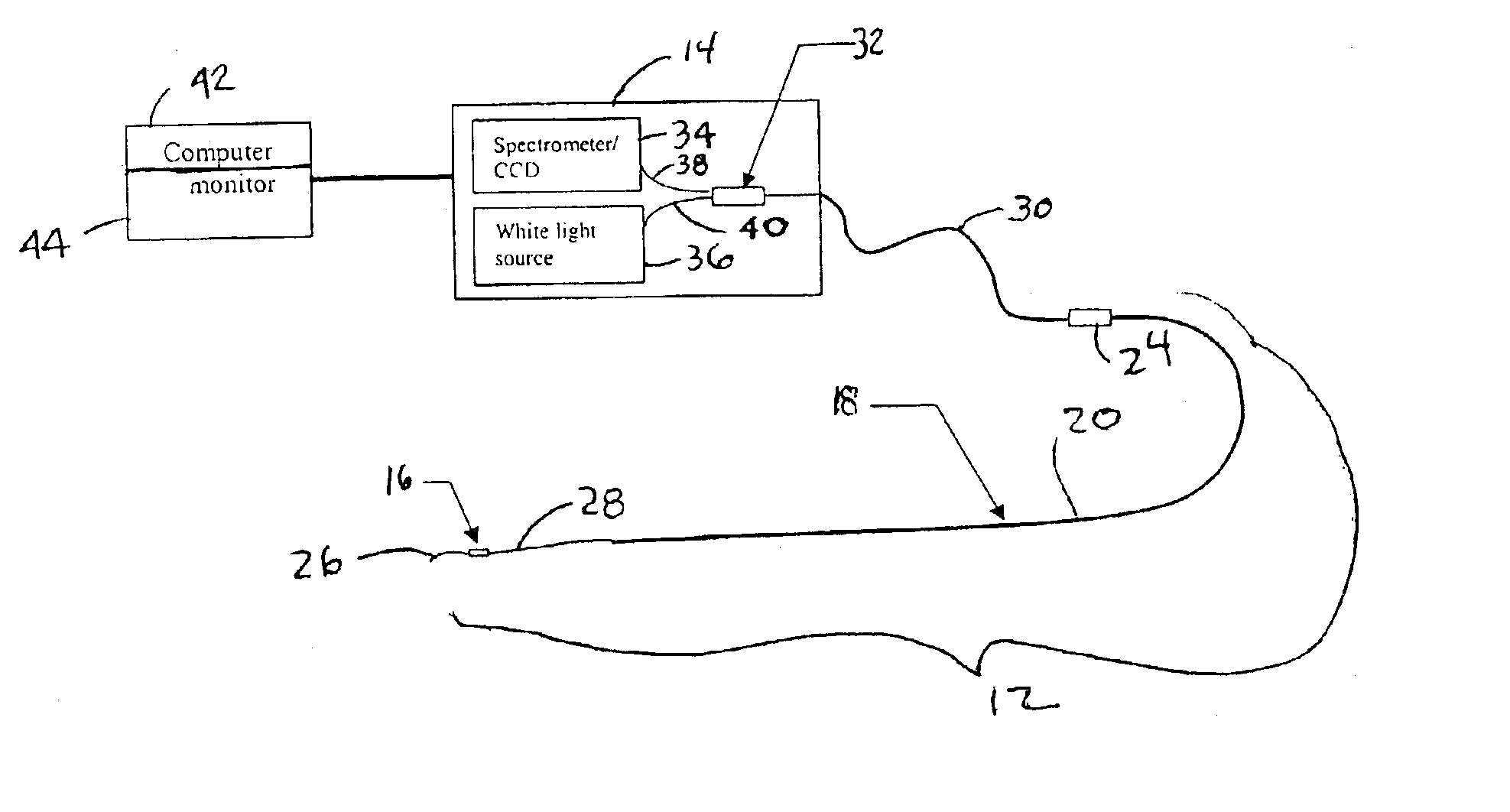
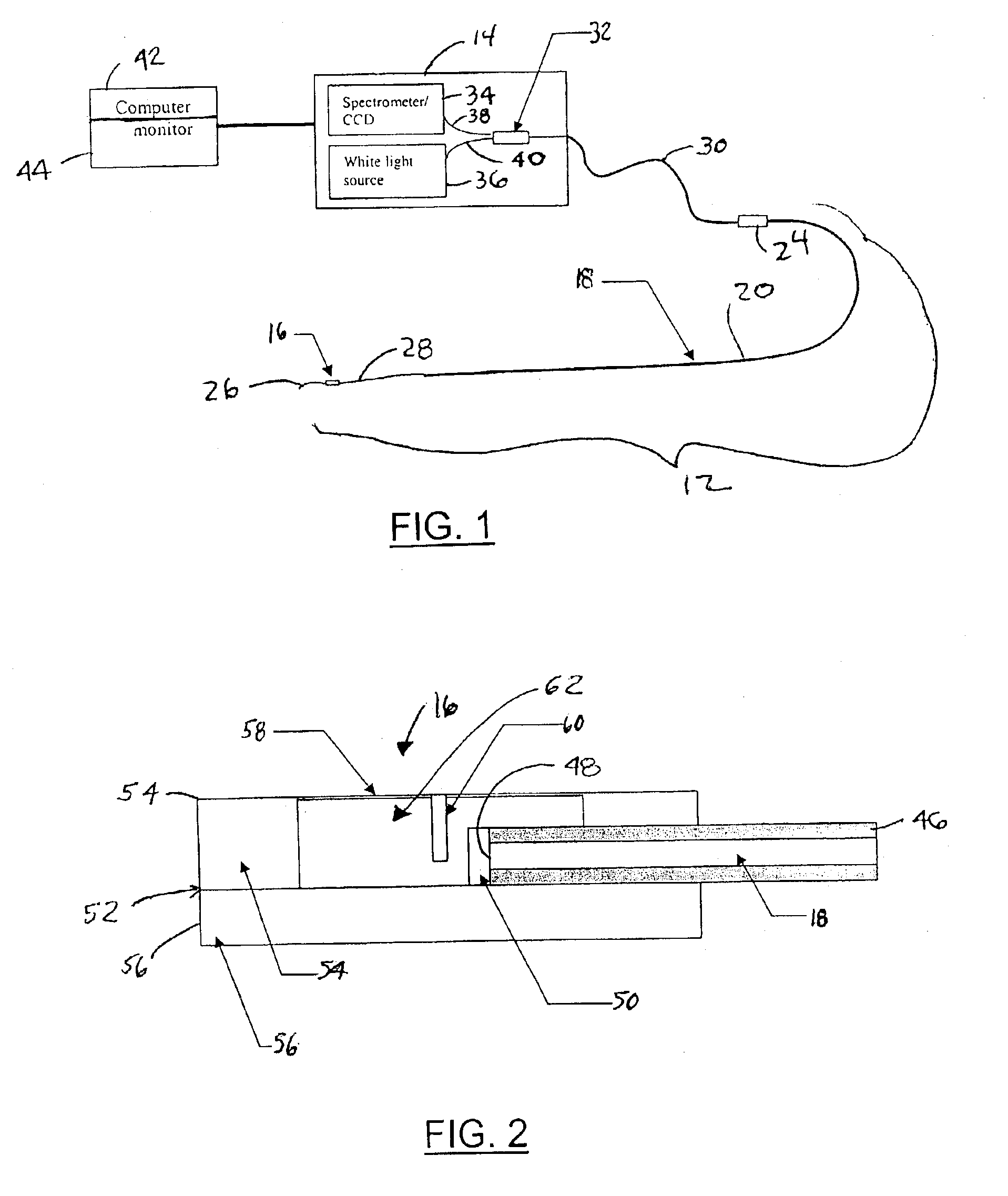
Referring now to FIG. 1, a pressure sensing system 10 has a sensor unit 12 and a light transmitting and receiving unit 14. Sensor unit 12 extends to the location in which the pressure is to be measured. Sensor unit 12 provides a spectral modulation of the light to light transmitting and receiving unit 14. Light transmitting and receiving unit 14 converts the modulation into the spectral fringe pattern and also converts into a pressure reading with a microprocessor (or sends the digitized signal of the fringe pattern to a computer to convert a pressure reading).

Sensor unit 12 comprises a sensor head 16, an optical fiber 18 within a guidewire 20, and a connecting system 2...


PUM


Abstract

The fiber optic pressure sensing system includes a sensor housing formed using MEMS processing. The sensor housing has ribs and grooves in both horizontal and vertical directions relative to the surface to allow the membrane to flex in a consistent manner. The flexing of the membrane allows the pedestal to be repeatedly positioned in response to pressure acting on the extension of the sensor head and membrane.

Description

TECHNICAL FIELDThe present invention relates generally to optical pressure sensors and, more specifically, to an ultra-miniature fiber optic pressure sensor embedded in an angioplasty guidewire.BACKGROUNDEach year in the United States, five million patients get initial diagnosis of a heart attack, and nearly one million patients undergo coronary angioplasty, or other interventional procedures, to open or restore flow through stenosed vessels. Angiography is the standard method for assessing lesion severity, but it only provides an anatomic view of the lumen of the vessel, often in only one plane. Clinical benefits, as well as other benefits, would result if a real-time assessment of the functional severity of the lesion and its effect on blood flow were possible. A current method for attempting to acquire this information is the Doppler guidewire via which flow (or flow velocity) can be measured at the lesion. For reliable measurements, a catheter must be accurately positioned and m...

Claims


Application Information

Patent Timeline
IPC IPC(8): G01L7/02G01L9/00G01L7/08G02B6/38G02B6/32
CPCG01L9/0042G01L9/0077G01L9/0047G02B6/3869G02B6/3855G02B6/32
Inventor SAWATARI, TAKEOKLOOSTER, ALEXASLAM, DEAN M.LIN, YUPINGMARKS, JAMES
Owner SENTEC CORP
Why Eureka
Try Eureka