Lithographic apparatus and device manufacturing method

a technology of lithographic apparatus and manufacturing method, which is applied in the direction of electrical apparatus, printers, instruments, etc., can solve the problems of high speed and therefore an expensive computer, and achieve the effect of improving throughpu

Inactive Publication Date: 2005-03-22
ASML NETHERLANDS BV
View PDF9 Cites 26 Cited by
  • Summary
  • Abstract
  • Description
  • Claims
  • Application Information

AI Technical Summary

Benefits of technology

It is an object of the present invention to provide a lithographic projection apparatus using a programmable patterning means which has improved throughput.
The use of a second programmable patterning means, set to have the same pattern by using the same data as the first programmable patterning means, to expose a second substrate, substantially doubles the throughput of the lithographic projection apparatus. This, in turn, improves the cost effectiveness of the apparatus. Present apparatus with two substrate tables have two stable positions which, according to this invention, can both be used for exposing substrates.
A single radiation system may be used, its projection beam of radiation being split to provide two beams, each patterned by one of the programmable patterning means. Advantageously, this reduces the cost of the lithographic projection apparatus. Alternatively, two radiation systems may be provided, one with each of the programmable patterning means. The capital cost of this apparatus would be greater but the beam intensity of each patterned beam would be greater than apparatus in which the beam of a single radiation system is split, thereby reducing the required exposure time and hence increasing the throughput of the apparatus.
The first and second substrate tables, first and second programmable pattern means and the first and second projection systems may be mounted on a common base frame, essentially creating a single unified apparatus. Alternatively, the first substrate table, the first programmable patterning means and the first projection system may be mounted on a first base frame with the second substrate table, the second programmable pattern means and the second projection system mounted on a second, separate, base frame. The latter arrangement effectively provides two separate apparatus reducing the risk of one part generating disturbances with affect the accuracy of the second part.

Problems solved by technology

To calculate this data from a file representing the mask pattern at the necessary rate is a difficult problem and requires a high speed, and therefore an expensive, computer.

Method used


Image

  • Lithographic apparatus and device manufacturing method
  • Lithographic apparatus and device manufacturing method

Examples


embodiment 1

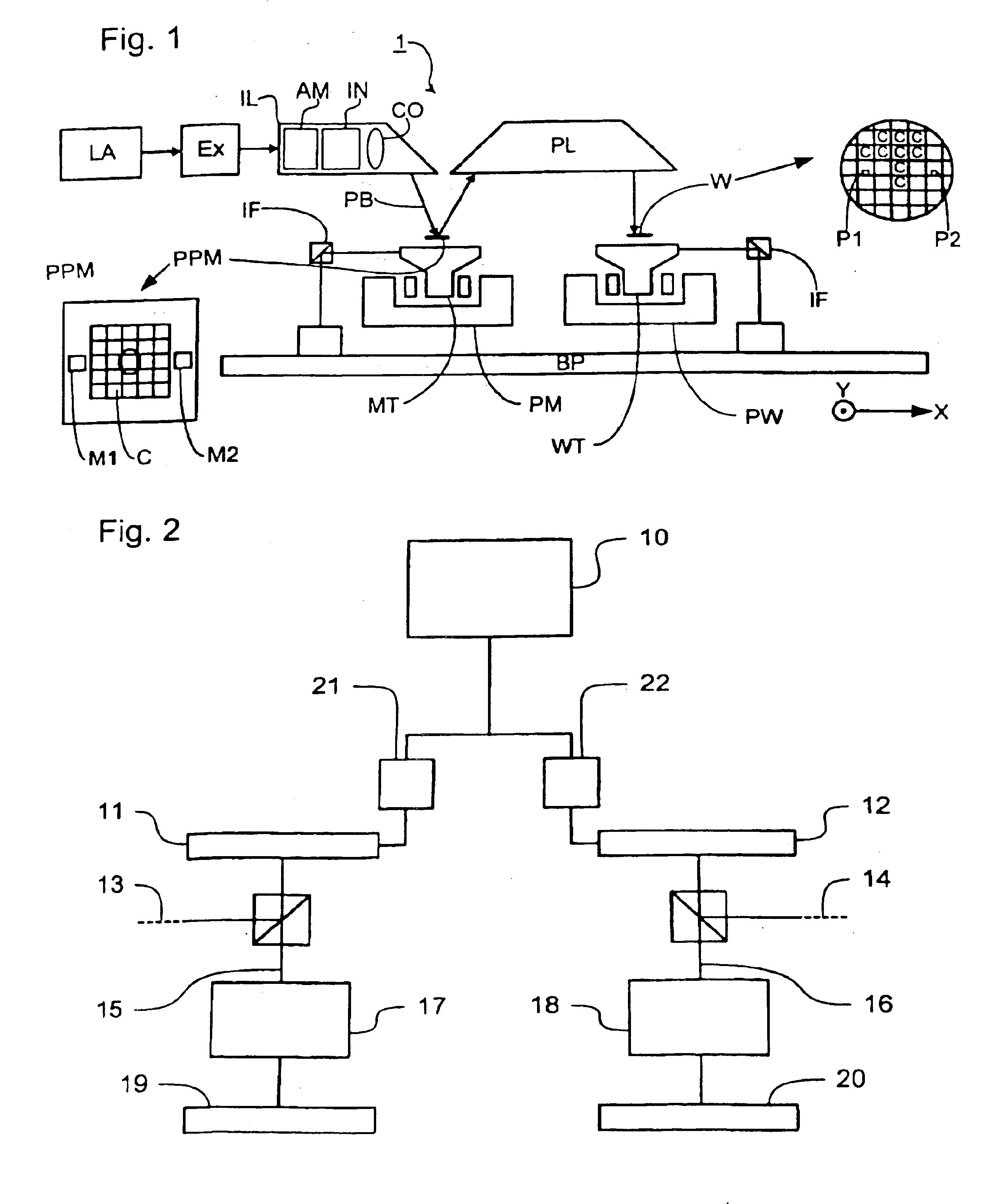
FIG. 1 schematically depicts a lithographic projection apparatus according to a particular embodiment of the invention. The apparatus comprises:a radiation system Ex, IL, for supplying a projection beam PB of radiation (e.g. UV radiation), which in this particular case also comprises a radiation source LA;a programmable patterning means PPM (e.g. a programmable mirror array) for applying a pattern to the projection beam; in general the position of the programmable patterning means will be fixed relative to item PL; however it may instead be connected to a positioning means for accurately positioning it with respect to item PL;an object table (substrate table) WT provided with a substrate holder for holding a substrate W (e.g. a resist-coated silicon wafer), and connected to positioning means for accurately positioning the substrate with respect to item PL;a projection system (“lens”) PL (e.g. a quartz and / or CaF2 lens system or a catadioptric system comprising lens elements made fro...


PUM

PropertyMeasurementUnit
wavelengthaaaaaaaaaa

Abstract

A lithographic apparatus uses the control signal from a computer to drive two spatial light modulators to pattern two separate projection beams for projection onto two substrates.

Description

BACKGROUND OF THE INVENTION1. Field of the InventionThe present invention relates generally to a lithographic projection apparatus and more particularly to a lithographic projection apparatus including two projection beams.2. Description of the Related ArtLithographic projection apparatus are used in the manufacture of integrated circuits (ICs), flat panel displays and other devices involving fine structures. The programmable patterning means generates a pattern corresponding to an individual layer of, for example, the IC, and this pattern is imaged onto a target portion (e.g. comprising part of, one or several dies) on a substrate (e.g. silicon wafer or glass plate) that has been coated with a layer of radiation-sensitive material (resist).Prior to this imaging step, the substrate may undergo various procedures, such as priming, resist coating and a soft bake. After exposure, the substrate may be subjected to other procedures, such as a post-exposure bake (PEB), development, a hard...

Claims


Application Information

Patent Timeline
Patent Type & Authority Patents(United States)
IPC IPC(8): G03F7/20H01L21/027
CPCG03F7/70991G03F7/70291H01L21/027
Inventor LIEBREGTS, PAULUS MARTINUS MARIABLEEKER, ARNO JANLOOPSTRA, ERIK ROELOFBORGGREVE, HARRY
Owner ASML NETHERLANDS BV
Why Eureka
Try Eureka