Spectrometer and method for measuring optical spectrum

a spectrometer and optical spectrum technology, applied in the field of spectrometers, can solve the problems of high cost, high cost, and high cost of devices, and achieve the effects of low capacitance of small detectors, small surface area, and high speed

Inactive Publication Date: 2005-03-22
VALTION TEKNILLINEN TUTKIMUSKESKUS
View PDF16 Cites 69 Cited by
  • Summary
  • Abstract
  • Description
  • Claims
  • Application Information

AI Technical Summary

Benefits of technology

The method and system of the invention provide several advantages. Since the solution utilizes the dispersive component twice, the measurement signal can be composed of a dispersed spectrum and imaged to the exit-slit as a very small image of the entrance slit, which enables the use of one detector with a small surface area. The capacitance of the small detector is low and the speed high, which enables high series-form analysis speed. With one detector the wavelength response is also temporally constant at different wavelengths. Since no macroscopically moving parts are needed, the function of the spectrometer is stable and environment resistant, and the spectrometer can be implemented using inexpensive wear-resistant components. The solution according to the invention can be integrated into a miniature spectroscope in which the influence of diffused light is reduced efficiently by means of the spectrometer structure.

Problems solved by technology

The device measures only one wavelength band at a time and thus wastes most of the optical power available.
Furthermore, this device requires a very accurate mechanical movement and its measurement, which are expensive.
The device also wears in use and is sensitive to thermal expansion, dirt and vibration.
Inaccuracy of movement of the grating and the drift of wavelength scale caused by it is a considerable error factor when the device is used for long-term quantitative or qualitative analysis of the chemical composition of samples in the NIR area (Near InfraRed).
Since this technique requires an interferometer which includes a moving mirror, it is extremely sensitive to interference in the environment, such as vibration and temperature changes.
Furthermore, modulation resulting from sample movement causes interference as a moving sample is measured.
This solution is, however, expensive, generates only a small amount of optical power and does not provide the advantage of multiplexing.
However, the row detector needed in the IR area in this solution is expensive, and furthermore, signal detection requires expensive and complex detection electronics.
Change of the wavelength area or resolution requirement often entails a new expensive row detector, which may constitute a vicious circle.
Since the wavelength responses of different elements in the row detector vary due to the deficiencies in the manufacturing process, their temperatures change at slightly different rates, which causes errors dependent on the wavelength and time.
For this reason thermal stabilization of the row detector is considerably more difficult than that of a single element detector and leads to expensive and heavy solutions in device implementations.
Since the grating that separates the wavelengths from one another spreads the image of the entrance slit on the modulator surface, the image to be produced therefrom is still too large, and thus the device requires a detector with a large surface area, which is expensive, often difficult to obtain and also has too high a capacitance, which results in slow function of the detector.
The fact that the detector is also dependent on the temperature also causes problems in this solution and thermal stabilization is needed.
Very cheap miniature spectrographs have been produced in large series using various mass production techniques (LIGA, etc.), but the problem related to these devices is that diffused light, which scatters from poor-quality optical surfaces and contains all wavelengths, spreads on the row detector surface and forms a level below which optical powers cannot be detected reliably.

Method used


Image

  • Spectrometer and method for measuring optical spectrum
  • Spectrometer and method for measuring optical spectrum
  • Spectrometer and method for measuring optical spectrum

Examples


Embodiment Construction

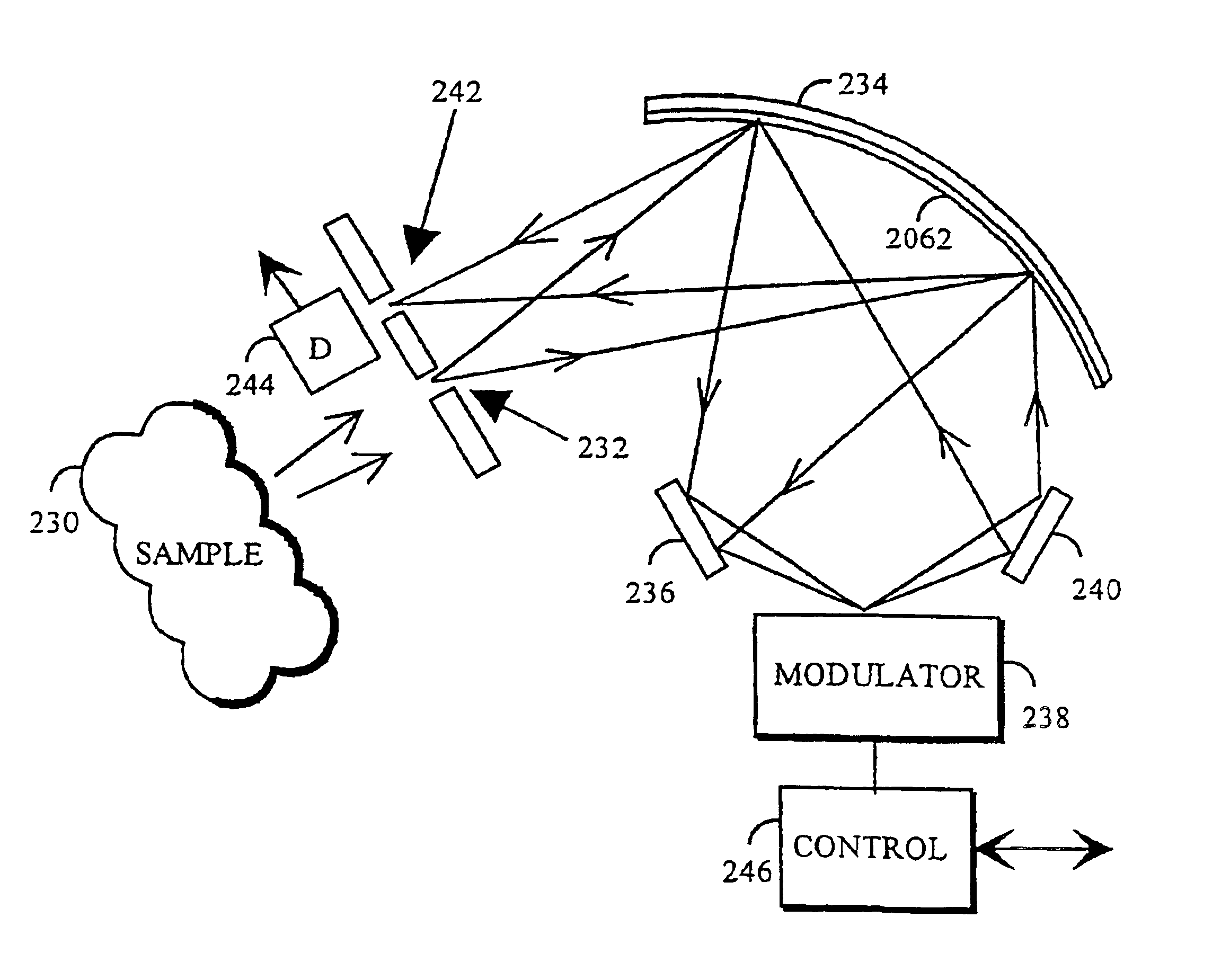
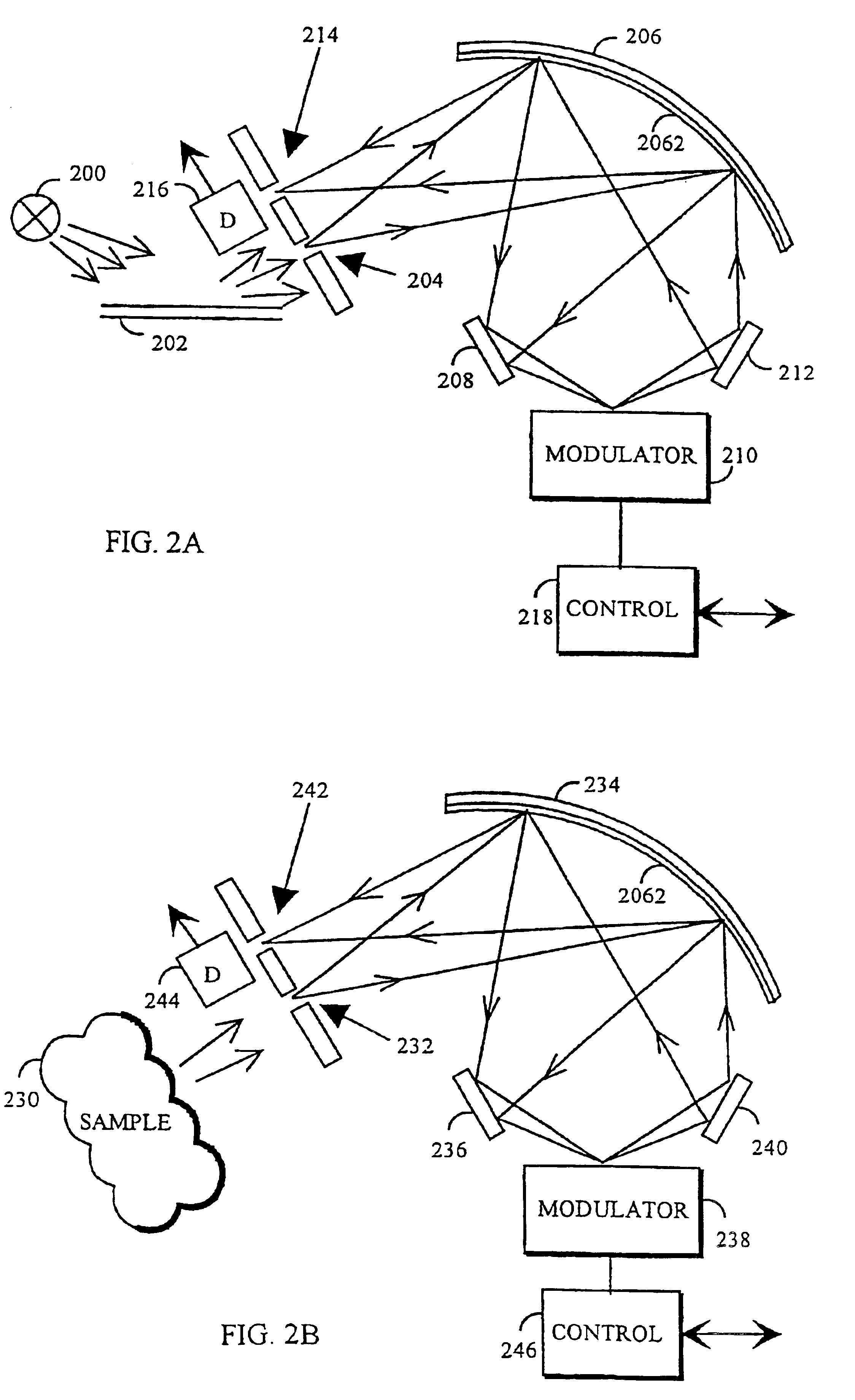
The measurement method and spectrometer according to the invention are particularly suitable for transmission and reflection measurements which are used for determining e.g. the concentration, thickness or temperature of substances, but the invention is not limited to these applications. The solution of the invention can be used for implementing an electrically controllable filter, which comprises sharp-edged pass bands and stop bands that can be selected in the desired manner, and which is utilized e.g. in research equipment. The solution of the invention can also be applied e.g. in automatic process analysers and sensors in which low price, small size and immunity to environment, for example, are important aspects.

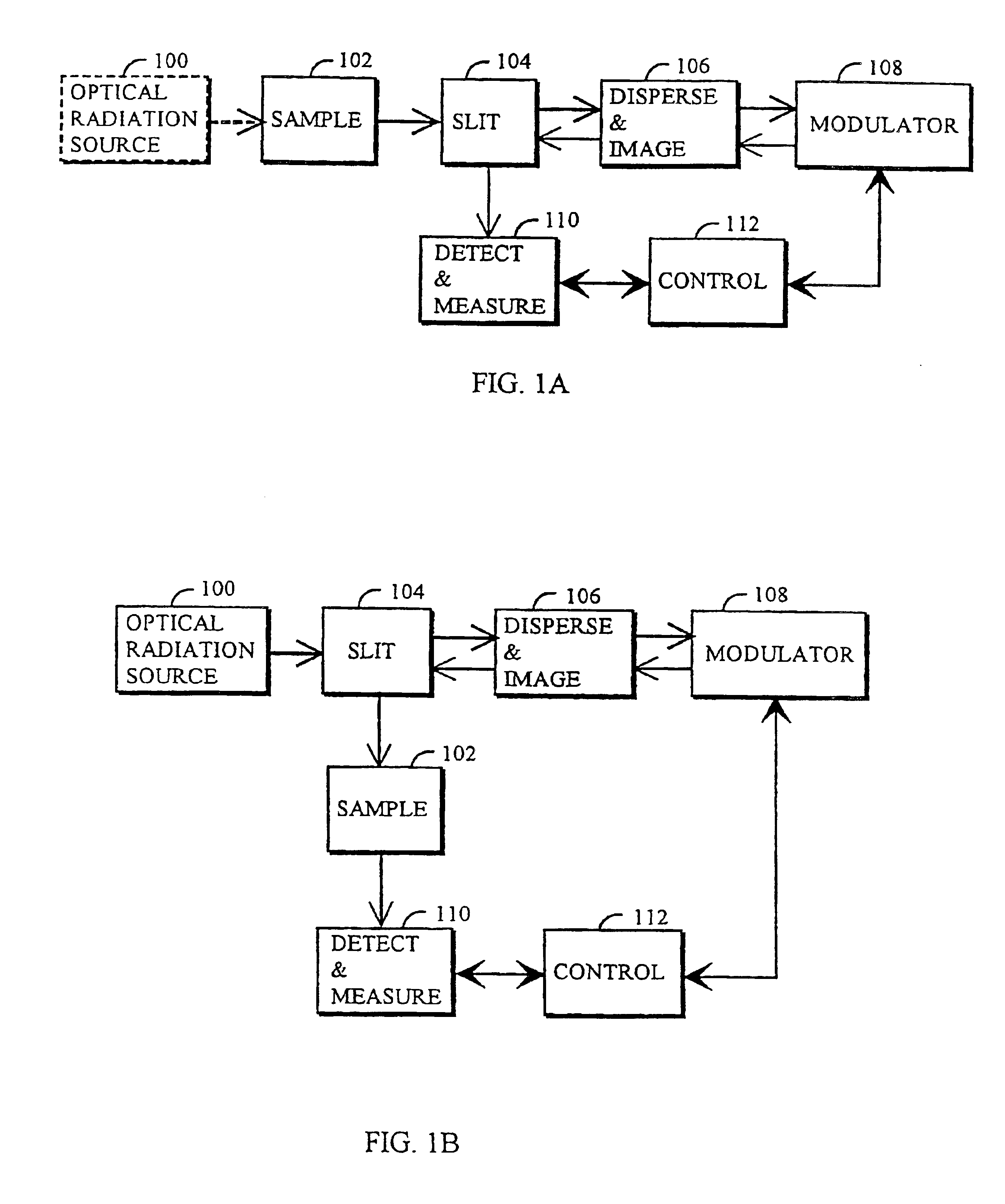
First the solution of the invention will be described with reference to FIG. 1A. Whether the spectrometer needs an optical power source 100 depends on the application. If the sample 102 is self-radiant, for example, the optical power source 100 is not necessary. The opti...


PUM


Abstract

An entrance slit of the spectrometer is illuminated with optical radiation. An optical component images the entrance slit to an optical modulator by the optical radiation and disperses the optical radiation into a spectrum. The spectrum is modulated by the optical modulator The optical component composes spectral non-dispersive measurement radiation of the spectrum and images the entrance slit included in the measurement radiation to an exit slit which may be the same one as the exit slit or a different one. Measurement radiation is detected from the entrance slit with a detector, which converts the measurement radiation into an electrical measurement signal.

Description

FIELD OF THE INVENTIONThe invention relates to spectrum measurement. In particular, the invention relates to a method of measuring an optical spectrum and to a spectrometer.BACKGROUND OF THE INVENTIONSpectrometers are used for analysing the wavelength distribution of the intensity of optical radiation. In scanning grating monochromators and prism monochromators the radiation to be measured is supplied into the device through an entrance slit and the radiation is dispersed by a grating and a prism by supplying one wavelength band at a time to a single element detector and registering the intensity spectrum of the radiation to be measured directly as a function of the movement of the grating or mirror. The device measures only one wavelength band at a time and thus wastes most of the optical power available. Furthermore, this device requires a very accurate mechanical movement and its measurement, which are expensive. The device also wears in use and is sensitive to thermal expansion,...

Claims


Application Information

Patent Timeline
Patent Type & Authority Patents(United States)
IPC IPC(8): G01J3/28
CPCG01J3/2846G01J3/28
Inventor TENHUNEN, JUSSIMALINEN, JOUKOKANSAKOSKI, MARKKU
Owner VALTION TEKNILLINEN TUTKIMUSKESKUS
Why Eureka
Try Eureka