
Cutting member

a technology of cutting member and cutting surface, which is applied in the field of cutting member, can solve the problems of the material cutting surface being worse, and achieve the effect of improving the wear resistance and plastic deformation resistance of the tool, and long service li

Inactive Publication Date: 2005-03-29
KYOCERA CORP
View PDF14 Cites 12 Cited by
  • Summary
  • Abstract
  • Description
  • Claims
  • Application Information

AI Technical Summary

Benefits of technology

A main object of the present invention is to provide a cutting member wherein the wear resistance and plastic deformation resistance are improved even in case of cutting hardly machinable materials such as stainless steel, thereby resulting in long service life of the tool.
Another object of the present invention is to provide a cutting member having improved chipping resistance.
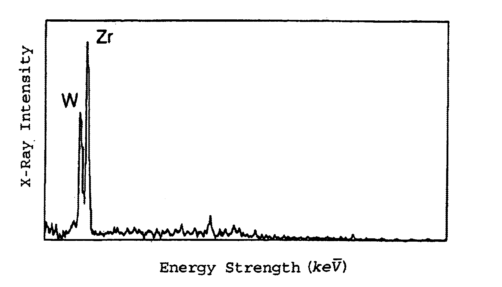
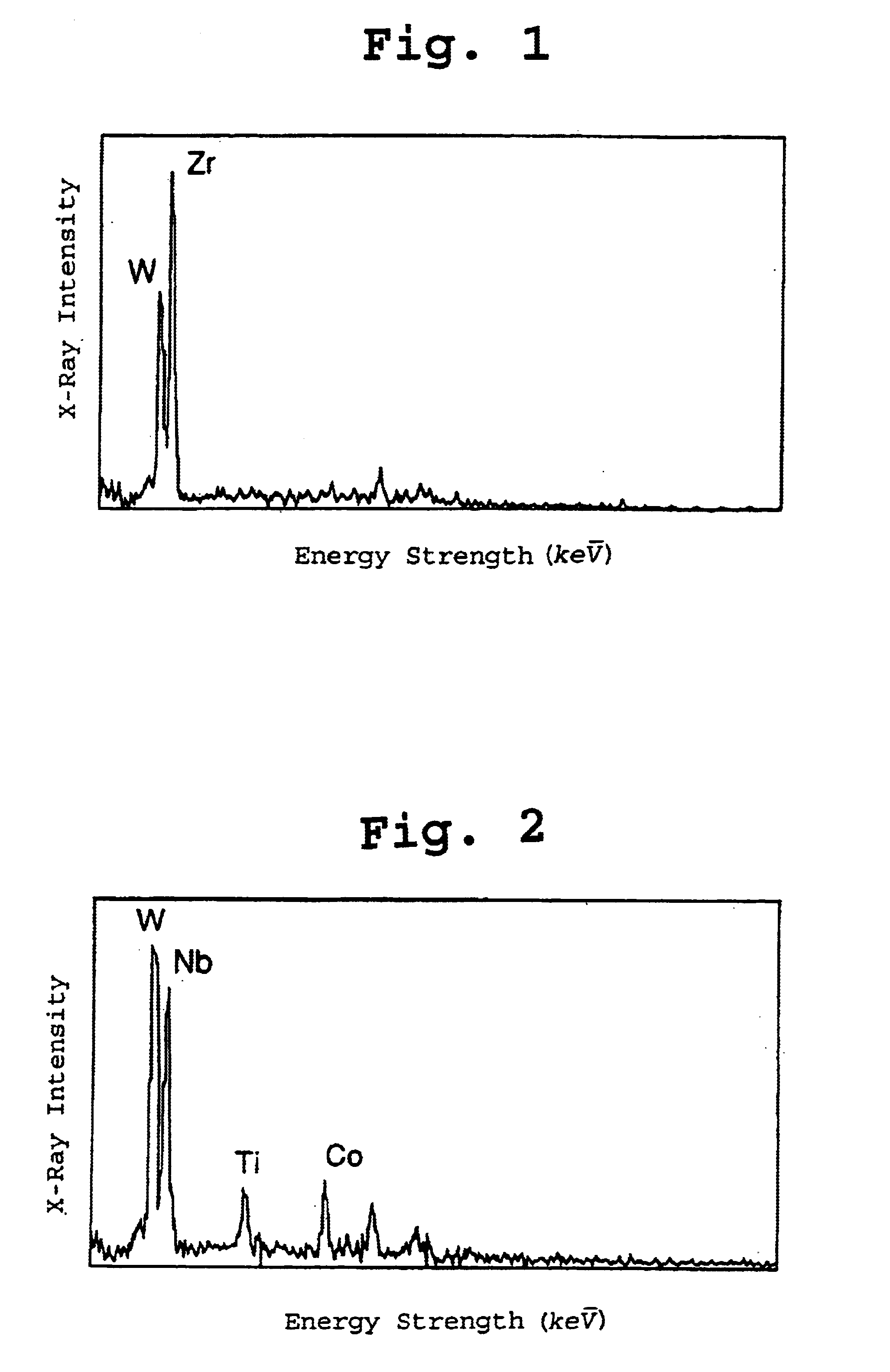
The present inventors have intensively studied to attain the objects described above. As a result, they found a new fact that, in case a solid solution having a high Nb or Zr content is precipitated and dispersed in the structure of a WC cemented carbide, it is made possible to obtain a cutting member which has an excellent mechanical strength because of high hardness of the precipitate and also has excellent wear resistance and plastic deformation resistance even in case of cutting hardly machinable materials such as stainless steel.
In case of a conventional cutting tool, chipping that may be caused by the adhesion of the material to be cut to the tool surface occurs, thereby making the machined surface of the material to be cut worse. However, according to the present invention, it is made possible to strengthen the cemented carbide itself by precipitating and dispersing a solid solution having a high Nb or Zr content and to improve the chipping resistance,

Problems solved by technology

In case of a conventional cutting tool, chipping that may be caused by the adhesion of the material to be cut to the tool surface occurs, thereby making the machined surface of the material to be cut worse.

Method used


Image

  • Cutting member
  • Cutting member

Examples


examples

The cutting member of the present invention will now be described in detail by way of examples.

example

The respective inorganic powders as raw powders shown in Table 1 were weighed in the proportion shown in the same table and, after mixing and pulverizing the powders, the mixed powders were formed into a green body having a desired shape of a cutting tool (CNMG432) by pressing and the green body was fired at 1773 K under reduced pressure of 10 Torr or less for one hour.

The resulting sintered body was cut at an arbitrary portion and the cross section thereof is ground and polished to obtain a mirror-like surface, and then a backscattered electron image was observed by an electron microscope. Then, the ratio of the area (area ratio) of the solid solution having a high Nb and / or Zr content to the whole solid solution structure was determined from the photograph of the backscattered electron image on the basis of difference in color between the solid solution having a high Nb and / or Zr content and the other solid solution in arbitrary region (20 μm×20 μm) using the image analysis method...


PUM

PropertyMeasurementUnit
Grain sizeaaaaaaaaaa
Fractionaaaaaaaaaa
Grain sizeaaaaaaaaaa

Abstract

The cutting member comprises WC, two or more solid solutions of WC and compounds selected from carbides, nitrides and carbonitrides of metals of the groups 4a, 5a and 6a in the Periodic Table, and at least one metal of the iron group; and at least one of the two or more solid solutions being a solid solution having a high Nb or Zr content, whereby the wear resistance and plastic deformation resistance are improved in case of cutting hardly machinable materials such as stainless steel, thereby making it possible to prolong the service life of the cutting member.

Description

THE FIELD OF THE INVENTIONThe present invention relates to a cutting member such as cutting tool, made of a high-strength and high-toughness tungsten carbide (WC) cemented carbide which has high wear resistance and high plastic deformation resistance and is particularly suited for cutting hardly machinable materials such as stainless steel which is hard to machine.BACKGROUND OF THE INVENTIONAs cemented carbides which have widely been used for cutting metals, there has hitherto been known a WC—Co alloy comprising a hard phase containing WC as a principal component and a bond phase made of a metal of the iron group such as cobalt, or an alloy obtained by adding carbides, nitrides or carbonitrides of metals of the groups 4a, 5a and 6a in the Periodic Table to the WC—Co alloy. In the latter case, grains of the solid solution of WC and carbides, nitrides and carbonitrides of metals of the groups 4a, 5a and 6a in the Periodic Table are added to the hard phase and bond phase.These cemented...

Claims


Application Information

Patent Timeline
IPC IPC(8): C23C30/00B23B27/14B22F7/00C22C29/08
CPCC23C28/044C23C30/005Y10T407/26Y10T407/27
Inventor SHIBATA, DAISUKE
Owner KYOCERA CORP
Learn More