Motor driving apparatus and motor using the same

a technology of motor driving and motor, which is applied in the direction of motor/generator/converter stopper, dynamo-electric converter control, stopping arrangement, etc., can solve the problems of increasing power loss (switching loss) generated at on/off of the driving transistor, reducing reliability, and reducing power loss. , to achieve the effect of reducing power loss and achieving higher rotational accuracy

Inactive Publication Date: 2005-03-29
MINEBEA MOTOR MFG
View PDF17 Cites 28 Cited by
  • Summary
  • Abstract
  • Description
  • Claims
  • Application Information

AI Technical Summary

Benefits of technology

The present invention addresses the problems discussed above, and aims to provide a motor driving apparatus that reduces power loss in accelerating a motor, and drives the motor at a high PWM frequency in rotating the motor at a regular r.p.m., thereby achieving a high rotational accuracy. Further the present invention provides a sophisticated and reliable motor driving apparatus that can prevent a negative current generated when the motor is decelerated.
As discussed above, this driving apparatus is equipped with the PWM frequency switch that changes the carrier frequency of the pulse-width modulator of the accelerating period to / from that of the regular rotating period. The carrier frequency of the pulse-width modulator is set at a lower frequency in the accelerating period than in the regular rotating period. This preparation allows reducing the power loss due to PWM chopping (switching) in accelerating the motor, and driving the motor at a high enough PWM frequency in the regular rotating period, thereby achieving accurate rotation.
In the motor acceleration including the start-up, the motor is driven in the synchronous rectification PWM mode, which is then switched to the single side PWM mode when the motor is decelerated or driven at a regular speed. This driving method allows further reducing the power loss, because the driving elements perform chopping at a lower PWM frequency in accelerating the motor, and on top of that, the synchronous rectification PWM mode is used. On the other hand, during the regular rotation of the motor, a higher rotational accuracy is obtainable due to a high enough PWM frequency.
Further, the synchronous rectification PWM mode is set not to be used at the timing when a change of an r.p.m. or a load of a motor feeds a braking current to the driving coils, thereby preventing the negative current from passing. As a result, various inconveniences possibly invited by the negative current can be avoided.

Problems solved by technology

As a result, a lot of power is lost in the flywheel diodes.
As a result, power loss (switching loss) generated at ON / OFF of the driving transistor increases, which entails heat generation in the elements thereby decreasing the reliability and yet increasing the power consumption.
In the synchronous rectification PWM driving, when a transistor in the upper arm and the counterpart transistor in the lower arm are turned on simultaneously, an undesirable flow-through current is generated in both the transistors.
In order to overcome this problem about the dead zone, expensive switching elements having excellent switching characteristics are needed or a complicated circuit is needed for realizing an accurate dead zone.
On top of that, when the negative current flows, the power supply voltage increases depending on an impedance of the power supply, and this voltage rise sometimes causes inconvenience to the motor, the motor driving apparatus, and the device incorporating those components.

Method used


Image

  • Motor driving apparatus and motor using the same
  • Motor driving apparatus and motor using the same
  • Motor driving apparatus and motor using the same

Examples


exemplary embodiment 1

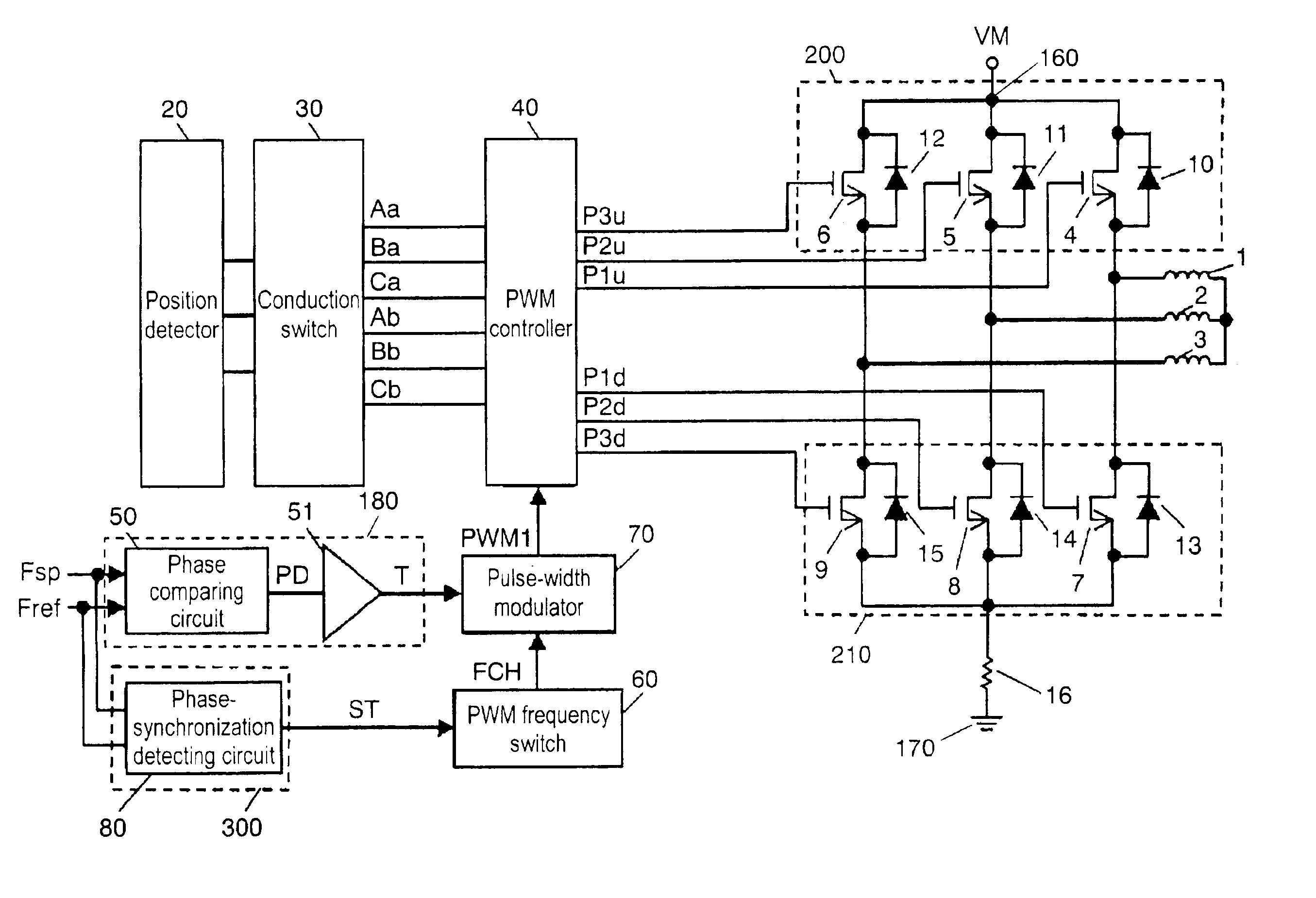
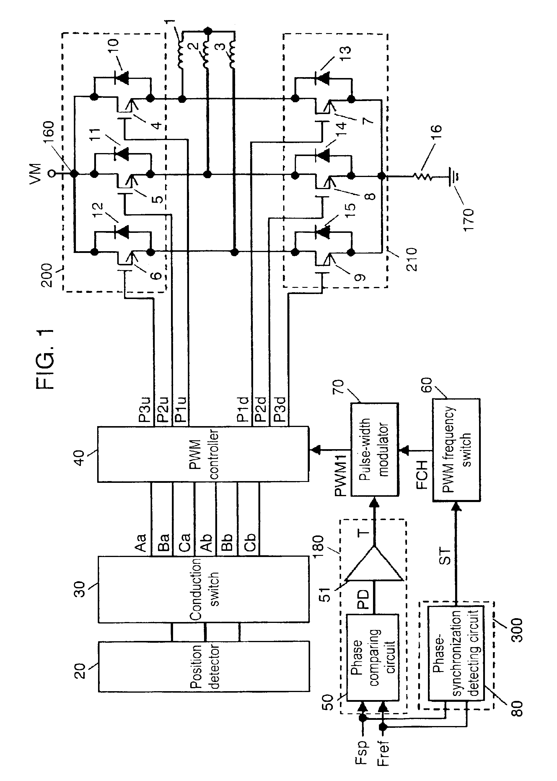
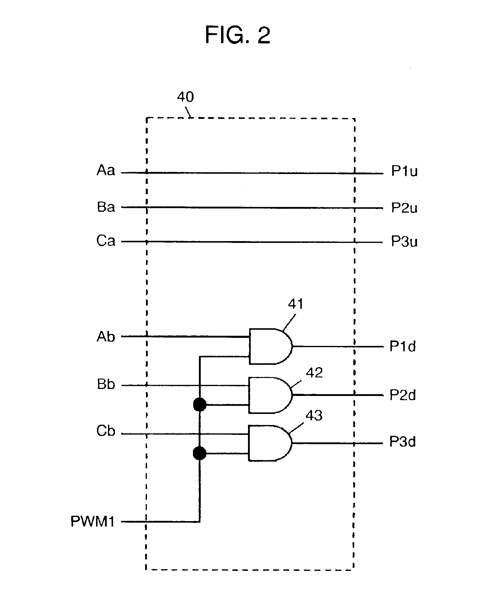
FIG. 1 shows a circuit diagram of a motor driving apparatus in accordance with the first exemplary embodiment of the present invention. FIG. 2 shows a circuit diagram of a PWM controller in the motor driving apparatus. FIG. 3A through FIG. 3C illustrate an operation of the motor driving apparatus. FIG. 4A through FIG. 4C show timing charts of signals of the motor driving apparatus. FIG. 5A and FIG. 5B show waveforms of driving coil currents of the motor driven by the driving apparatus.

In FIG. 1, a three-phase motor is taken as an example of a brush-less motor (hereinafter simply referred to as a motor) driven by the driving apparatus of the present invention. The three-phase motor includes driving coils 1, 2, and 3 which are wound on respective stator cores disposed opposite to rotor magnets (not shown) of the motor. Respective drains of driving transistors 4, 5 and 6 are coupled to first power source line 160 connected to power source terminal VM. A source of transistor 4 is connec...

exemplary embodiment 2

FIG. 6 shows a circuit diagram of a motor driving apparatus in accordance with the second exemplary embodiment of the present invention. FIG. 7 shows a circuit diagram of a PWM controller in the motor driving apparatus. FIG. 8A through FIG. 8C illustrate an operation of the motor driving apparatus. FIG. 9A through FIG. 9C show timing charts of signals of the motor driving apparatus. FIG. 10A and FIG. 10B are schematic drawings showing current paths of driving-coil currents of the motor driven by the driving apparatus.

In this second embodiment, similar elements to those in the first embodiment have the same reference marks, and the descriptions thereof are omitted here. In FIG. 6, the second embodiment differs from the first one in the following points: A first input terminal of comparator 53 receives an output from error-amplifying circuit 51 of torque instructor 180. A second input terminal of comparator 53 is coupled to a second terminal of reference power supply 54 of which first...

exemplary embodiment 3

FIG. 11 shows a motor and its driving apparatus in accordance with the third exemplary embodiment of the present invention. In FIG. 11, driving coils 1-3 of motor 150 are coupled to driving apparatus 100, which is connected between first power-supply line 160 connected to power-supply terminal VM and second power-supply line 170 connected to the grounding.

Driving apparatus 100 uses the driving apparatus described in the first or the second embodiment, so that the motor in accordance with the third embodiment can utilize the advantages produced in the first or the second embodiment.

As the first through the third embodiments tell, the present invention provides a motor driving apparatus that can reduce the power loss caused by PWM chopping (switching) during the acceleration of a motor, and drive the motor accurately at a high enough PWM frequency during the regular rotating period. The present invention also provides a motor using the foregoing driving apparatus.

A PWM controller is e...


PUM


Abstract

A motor driving apparatus includes a pulse-width modulator and a PWM frequency switch for switching a carrier frequency of the modulator. The PWM frequency switch changes a carrier frequency in a start-up period of the motor to another frequency when the motor enters into a regular rotation. The carrier frequency in the start-up period is set at a lower level than that in the regular rotation period, so that the driving apparatus can reduce power-loss generated in the start-up period by switching actions of respective driving elements forming a first and a second drivers. In the regular rotation period, the driving apparatus performs PWM-driving with a high enough carrier frequency, so that the motor driven by this driving apparatus can realize accurate rotation.

Description

FIELD OF THE INVENTIONThe present invention relates to a motor driving apparatus using a pulse-width modulation (hereinafter referred to as PWM) driving method, which is used, e.g., in the field of information devices.BACKGROUND OF THE INVENTIONA conventional PWM motor driving apparatus disclosed in Japanese Patent Application Non-examined Publication No. H05-38184 is known as realizing low power consumption of a brush-less motor (hereinafter simply referred to as a motor). FIG. 12 shows a structure of a conventional motor driving apparatus. In FIG. 12, position detecting element 1500 uses, e.g., Hall elements. Each one of those position detecting elements 1500 detects a position of respective rotor magnets (not shown) of the motor, and outputs a detection signal to conductive state instructing-circuit 1300 via position detecting circuit 1400. Instructing circuit 1300 outputs timing signals UHo, VHo, WHo, UL, VL, and WL in order to switch driving coils 1, 2 and 3.Phase comparator 12...

Claims


Application Information

Patent Timeline
Patent Type & Authority Patents(United States)
IPC IPC(8): H02P6/00H02P6/08H02P6/24H02P6/18H02P6/14H02P6/20H02P7/00H02P1/40H02P6/06H02P6/17H02P23/16H02P27/06H02P27/08
CPCH02P27/08H02P1/40
Inventor SEIMA, TOSHIAKIYOKOUCHI, TOMOHARU
Owner MINEBEA MOTOR MFG
Why Eureka
Try Eureka