High frequency module

a high frequency module and module technology, applied in the field of high frequency modules, can solve the problems of high frequency filter and high frequency splitter being susceptive to heat, not only with saws (surface acoustic wave) devices, but also with fbars (film bulk acoustic resonators), baws (bulk acoustic filters), and conventional high frequency modules with a unitary structure incorporating high frequency power amplifier devices, etc., to achieve the effect o

Inactive Publication Date: 2005-03-29
KYOCERA CORP
View PDF11 Cites 154 Cited by
  • Summary
  • Abstract
  • Description
  • Claims
  • Application Information

AI Technical Summary

Benefits of technology

[0010]A primary object of the present invention is to provide a small size, high performance, low cost high frequency module capable of keeping the filter component free from the influence of heat radiated by the power amplifier device with high power that is located in the vicinity thereof, and maintaining the high frequency filtering characteristics of the filter component.

Problems solved by technology

However, such high frequency filters and high frequency splitters are susceptive to heat.
In addition, this problem is not only with SAW (Surface Acoustic Wave) devices but also with FBARs (Film Bulk Acoustic Resonator) and BAWs (Bulk Acoustic Wave Filter).
For this reason, conventional high frequency modules with a unitary structure incorporating the high frequency power amplifier device, the high frequency filter or the like are unable to sufficiently meet the recent demand for miniaturization, lightening, high density packaging, and cost reduction of mobile communication terminals and the like.

Method used


Image

  • High frequency module
  • High frequency module
  • High frequency module

Examples


example

[0137]The present invention is hereinafter described in detail on the basis of the following example and comparative example.

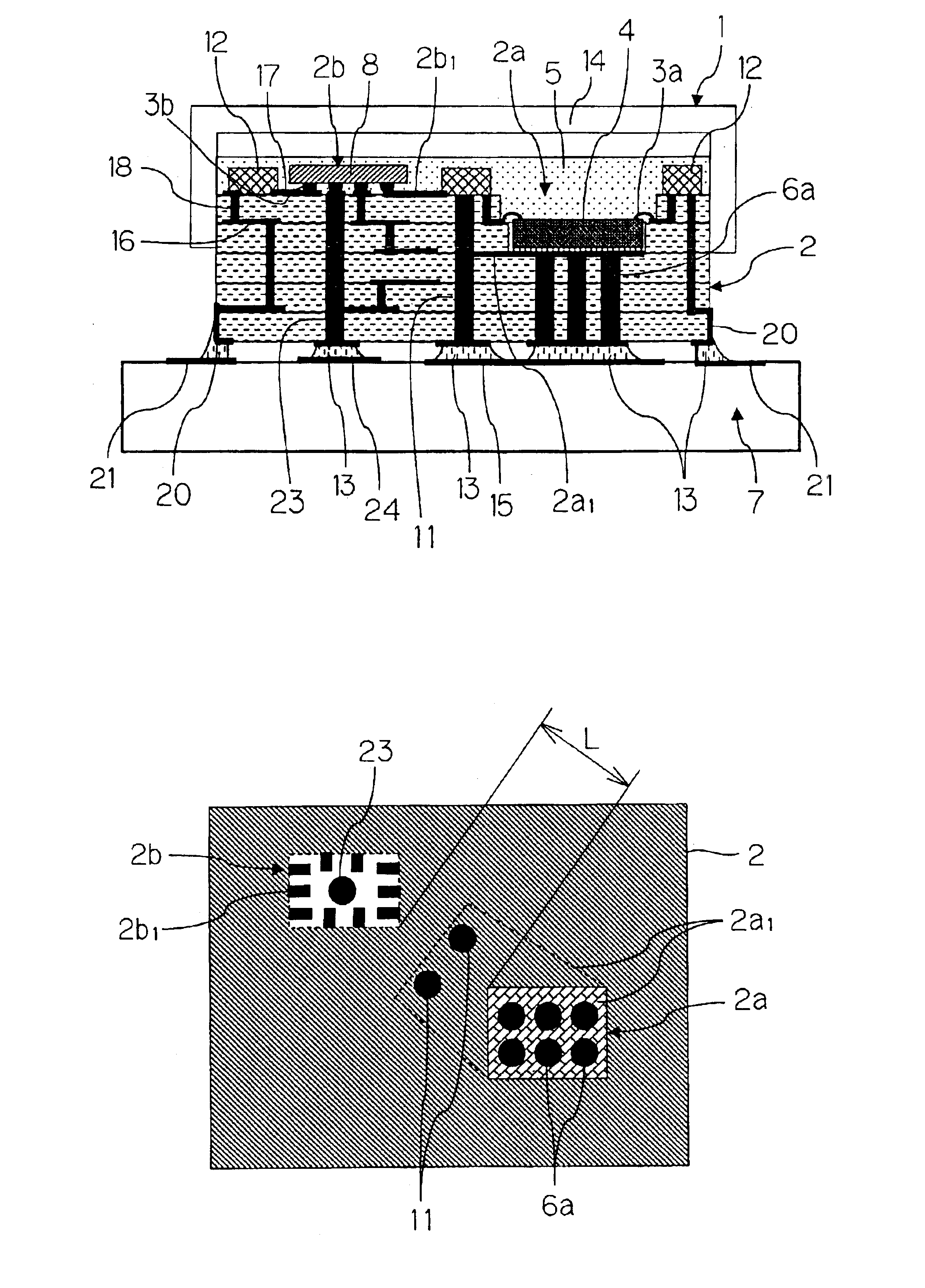
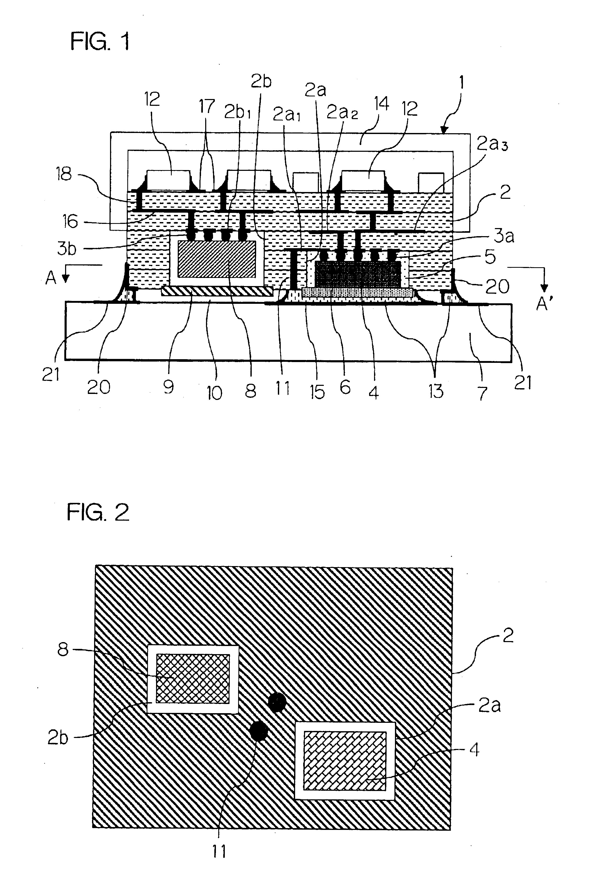
[0138]A glass-ceramic-based dielectric material comprising a borosilicate glass and alumina and having a thermal conductivity of 3-5 W / m·K was used as the dielectric material. For the through-hole conductors, an Ag-based conductive material with a thermal conductivity of 150 W / m·K was used. A high frequency module was fabricated as previously described. This high frequency module was mounted using a Cu—Ag-based brazing material onto the surface of a motherboard having an insulating substrate that was composed of a glass woven cloth-epoxy resin composite material and having a thermal dissipation conductor and a signal wiring layer made of copper formed thereon.

[0139]The conditions were set up so that with the source ON / OFF ratio (Duty cycle) of the power amplifier device (PA) being 1 / 8, an output of 33.5 dBm be obtained from an input signal of 0 dB, and the ste...


PUM


Abstract

There is presented a high frequency module, in which a recess 2a for mounting power amplifier device is formed on a lower surface of a dielectric substrate 2, and a recess 2b for mounting surface acoustic wave filter is formed on an upper surface of the dielectric substrate 2, and a power amplifier device 4 and a surface acoustic wave filter 8 are mounted through conductive bumps 3a and 3b on the recesses 2a and 2b, respectively. In addition, a through-hole conductor 11 whose one end is exposed at the lower surface of the dielectric substrate 2 is provided between the recesses 2a and 2b. The exposed end of the through-hole conductor 11 is attached to a thermal dissipation conductor 15 on an upper surface of an external electric circuit board 7 through a brazing material 13.

Description

[0002]This application is based on applications No. 2002-50251 and No. 2002-120812 filed in Japan, the content of which is incorporated hereinto by reference.BACKGROUND OF THE INVENTION[0003]1. Field of the Invention[0004]The present invention relates to a high frequency module used for electronic apparatuses and electronic devices including portable information terminals, wireless LANs, WLLs (Wireless Local Loop). In particular, this invention relates to a small size, high performance, low cost high-frequency module with a unitary structure incorporating a high frequency amplification device together with a high frequency filter or a high frequency splitter.[0005]2. Description of the Related Art[0006]A high frequency module generally includes inside a high frequency power amplifier device, and a high frequency filter or a high frequency splitter disposed in the vicinity of the power amplifier device.[0007]With the recent increase in transmission capacity and transmission speed in ...

Claims


Application Information

Patent Timeline
Patent Type & Authority Patents(United States)
IPC IPC(8): H01L23/58H01L23/66H05K1/02H05K3/40H05K1/00H05K3/34H05K1/18H05K1/14H05K1/03H01L23/36H01L23/367H01L23/538
CPCH01L23/3677H01L23/5389H01L23/66H05K1/0206H01L23/36H01L2224/16225H01L2224/32225H01L2224/48091H01L2224/48227H01L2224/73265H01L2924/01012H01L2924/0102H01L2924/01046H01L2924/01078H01L2924/01079H01L2924/09701H01L2924/15153H01L2924/1517H01L2924/15313H01L2924/1532H01L2924/16152H01L2924/16195H01L2924/19041H01L2924/19105H01L2924/19106H01L2924/30107H01L2924/3025H05K1/0237H05K1/0298H05K1/0306H05K1/141H05K1/183H05K1/185H05K3/3442H05K3/4053H05K2201/10083H05K2201/10674H01L24/48H01L2924/01019H01L2924/01068H01L2224/73253H01L2924/15192H01L2924/1306H01L2224/16235H01L2924/13062H01L2924/12032H01L2924/00014H01L2924/00012H01L2924/00H01L2924/12036H01L24/73H01L2224/05599H01L2224/45099H01L2224/85399H01L2924/181H03H9/0538H01L2224/45015H01L2924/207
Inventor IKUTA, TAKANORIKITAZAWA, KENJI
Owner KYOCERA CORP
Why Eureka
Try Eureka