Apparatus for detecting peaks of wavelength-division-multiplexed light, and apparatus for controlling said light

a technology of wavelength-division multiplexed light and apparatus, applied in the direction of electromagnetic repeaters, transmission monitoring, instruments, etc., can solve the problems of reducing the cost of optical transmission systems, affecting the transmission quality, and deploying a level detector or level controller for each wavelength at all repeater stages, etc., and achieves the effect of simple structur

Inactive Publication Date: 2005-03-29
FUJITSU LTD
View PDF9 Cites 13 Cited by
  • Summary
  • Abstract
  • Description
  • Claims
  • Application Information

AI Technical Summary

Benefits of technology

Accordingly, an object of the present invention is to provide an apparatus for detecting and an apparatus for controlling wavelength-division-multiplexed light in which it is possible, through a simple structure and without requiring a costly wavelength demultiplexer, and independently of

Problems solved by technology

In such WDM transmission systems, management of the optical level of each channel in the transmission line is important, and the advantages and disadvantages of such management affect greatly the operating state of such functional devices as optical amplifiers, and this in turn changes transmission quality significantly.
However, deploying a level detector or level controller for each wavelength at all repeater stages is inappropriate from the standpoint of reducing the cost of optical transmission systems.
Consequently, this arrangement is not suited to an apparatus for detecting and controlling wavelength-division-multiplexed ligh

Method used


Image

  • Apparatus for detecting peaks of wavelength-division-multiplexed light, and apparatus for controlling said light
  • Apparatus for detecting peaks of wavelength-division-multiplexed light, and apparatus for controlling said light
  • Apparatus for detecting peaks of wavelength-division-multiplexed light, and apparatus for controlling said light

Examples


first embodiment

(a) First Embodiment

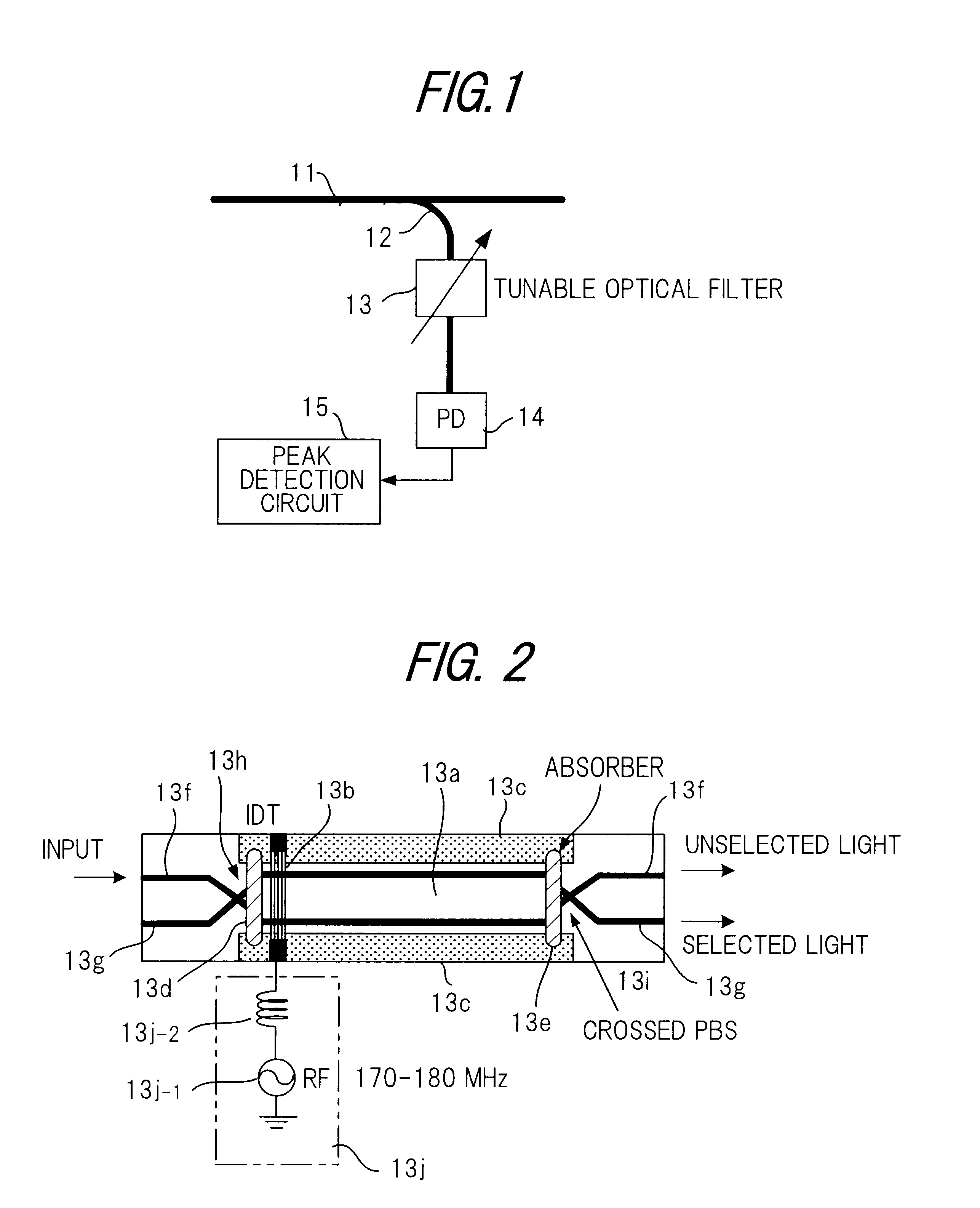
FIG. 7 is a diagram showing the construction of a first embodiment of an apparatus for controlling wavelength-division-multiplexed light according to the present invention. The apparatus includes an optical fiber 21 through which wavelength-division-multiplexed light propagates; an optical branching coupler 22 for branching the wavelength-division-multiplexed light; a wavelength-division-multiplexed light peak detector 23 for detecting the peaks of wavelength-division-multiplexed light; and a device 24, such as a variable light attenuator, for controlling the optical level of output light. Examples of the device for controlling the optical level of output light are, in addition to the variable light attenuator, an external optical modulator and a semiconductor optical amplifier.

The wavelength-division-multiplexed light peak detector 23 has a structure identical with that of the apparatus for detecting the peaks of wavelength-division-multiplexed light shown in FI...

second embodiment

(b) Second Embodiment

FIG. 8 is a diagram showing the construction of a third embodiment of an apparatus for controlling wavelength-division-multiplexed light according to the present invention. Components in FIG. 8 identical with those of the first embodiment shown in FIG. 7 are designated by like reference characters. The second embodiment shown in FIG. 8 differs from the first embodiment in that an optical-fiber amplifier is used instead of the variable light attenuator as means for controlling the level of the output light.

As shown in FIG. 8, there are provided optical isolators 25, 26; a wavelength multiplexing coupler 27 for multiplexing excitation light and signal light; an optical amplifying fiber 28, such as erbium-doped fiber (EDF), for amplifying signal light; and a laser diode (excitation light source) 29 for generating excitation wavelength light the wavelength of which is shorter than that of the signal light but the energy of which is greater, and inputting this light ...

third embodiment

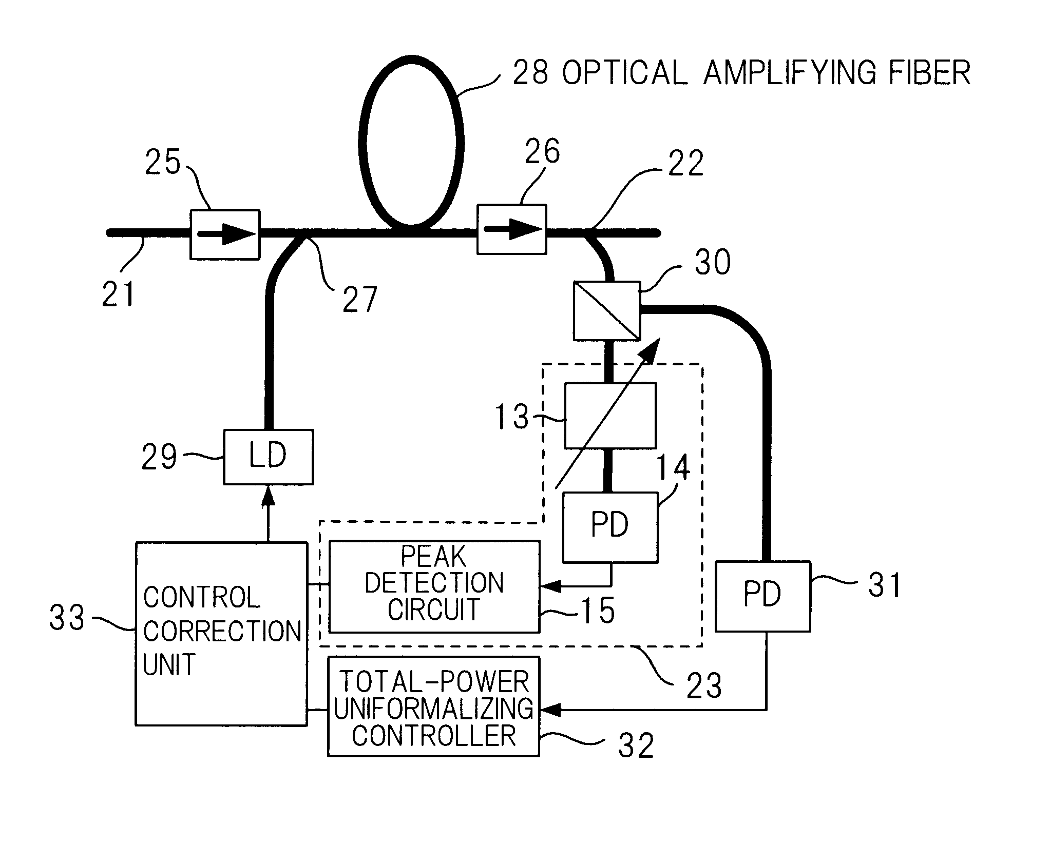
(c) Third Embodiment

FIG. 9 is a diagram showing the construction of a third embodiment of an apparatus for controlling wavelength-division-multiplexed light according to the present invention. Components in FIG. 9 identical with those of the second embodiment shown in FIG. 8 are designated by like reference characters. The third embodiment shown in FIG. 9 differs from the second embodiment in that (1) a control loop for uniformalizing maximum value and a control loop for uniformalizing total power are provided as means for controlling the level of output light, and (2) control for uniformalizing maximum value and control for uniformalizing total power is performed appropriately based upon the difference between the maximum peak value and set peak value.

According to the first and second embodiments, control is carried out on the assumption that the level error of each channel (the light of each wavelength) is small. However, depending upon conditions, there are cases where the maximu...


PUM


Abstract

Disclosed is an apparatus for controlling wavelength-division-multiplexed light wherein overall power of wavelength-division-multiplexed light is rendered constant through control for uniformalizing the level of only one wave of maximum power, and wherein the levels of respective channels are made substantially uniform. Optical level control means controls the optical level of propagating wavelength-division-multiplexed light, and a portion of the wavelength-division-multiplexed light output from the output level control means is branched to a tunable optical filter, which selectively outputs the light of each wavelength contained in the wavelength-division-multiplexed light. The light of each wavelength output from the optical filter is photoelectrically converted to an electric signal by photoelectric conversion means. Peak detection means detects the maximum peak value of the electric signal output from the photoelectric conversion means, and a feedback signal is input to the optical level control means in such a manner that the maximum peak value becomes a set value.

Description

BACKGROUND OF THE INVENTIONThis invention relates to an apparatus for detecting the peaks of wavelength-division-multiplexed light and an apparatus for controlling this light. More particularly, the invention relates to a peak detection apparatus for detecting the peaks of wavelength-division-multiplexed light and a control apparatus for controlling the intensity of wavelength-division-multiplexed light based upon maximum peak value.The development of multimedia networks in recent years has been accompanied by increasing demand for information, and much greater capacity and more flexible network formation are being sought for trunk-line optical transmission systems where information is concentrated. At the present time, transmission using wavelength division multiplexing (WDM) is the most effective means of coping with system demand and has been implemented commercially mainly in North America. In such WDM transmission systems, management of the optical level of each channel in the ...

Claims


Application Information

Patent Timeline
IPC IPC(8): H04B10/17H04J14/02H04B10/08G02B6/00H04B10/07H04B10/29H04B10/296H04J14/00
CPCH04B10/077H04J14/0221H04B10/291H04B10/07955
Inventor SUGAYA, YASUSHI
Owner FUJITSU LTD
Why Eureka
Try Eureka