Magnetoresistive transducer having stronger longitudinal bias field

a technology of magnetoresistive transducers and longitudinal bias fields, which is applied in the field of magnetoresistive transducers, can solve the problems that the barkhausen noise cannot be sufficiently reduced in the magnetoresistive transducer, and achieve the effects of reducing the intensity of the magnetic pole generated at the tip end of the domain control layer, enhancing the longitudinal bias field, and suppressing the magnetic flux from the domain control layer into the raised portion

Inactive Publication Date: 2005-04-05
FUJITSU LTD
View PDF17 Cites 8 Cited by
  • Summary
  • Abstract
  • Description
  • Claims
  • Application Information

AI Technical Summary

Benefits of technology

[0019]In general, it is impossible to avoid generation of a raised portion swelling from the lower surface of the upper shield layer toward the magnetoresistive film unless the thickness of the domain control layer or a lead layer, stacked on the domain control layer, can significantly be reduced. The magnetization of the upper shield layer tends to terminate at any side end surface of the raised portion. This means that the magnetic poles tend to appear at the end surface of the raised portion. When the magnetization can be established in the reverse direction in the upper shield layer i

Problems solved by technology

However, the Barkhausen noise in fact cannot sufficiently be reduced in the magnetoresi

Method used


Image

  • Magnetoresistive transducer having stronger longitudinal bias field
  • Magnetoresistive transducer having stronger longitudinal bias field
  • Magnetoresistive transducer having stronger longitudinal bias field

Examples


third embodiment

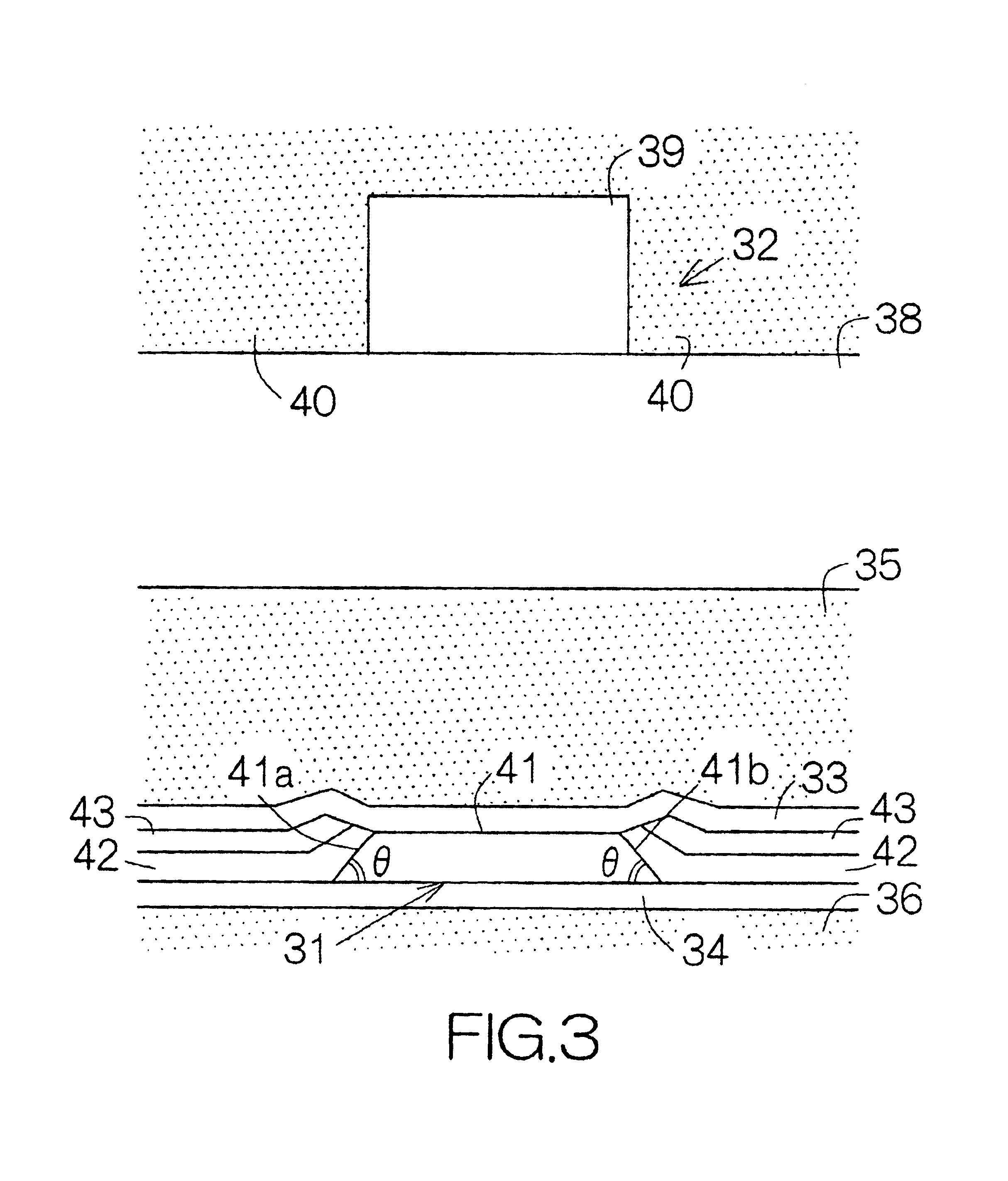
e rear / write eletromagnetic transducer for illustrating the structure of a magnetoresistive (MR) element according to the present invention;

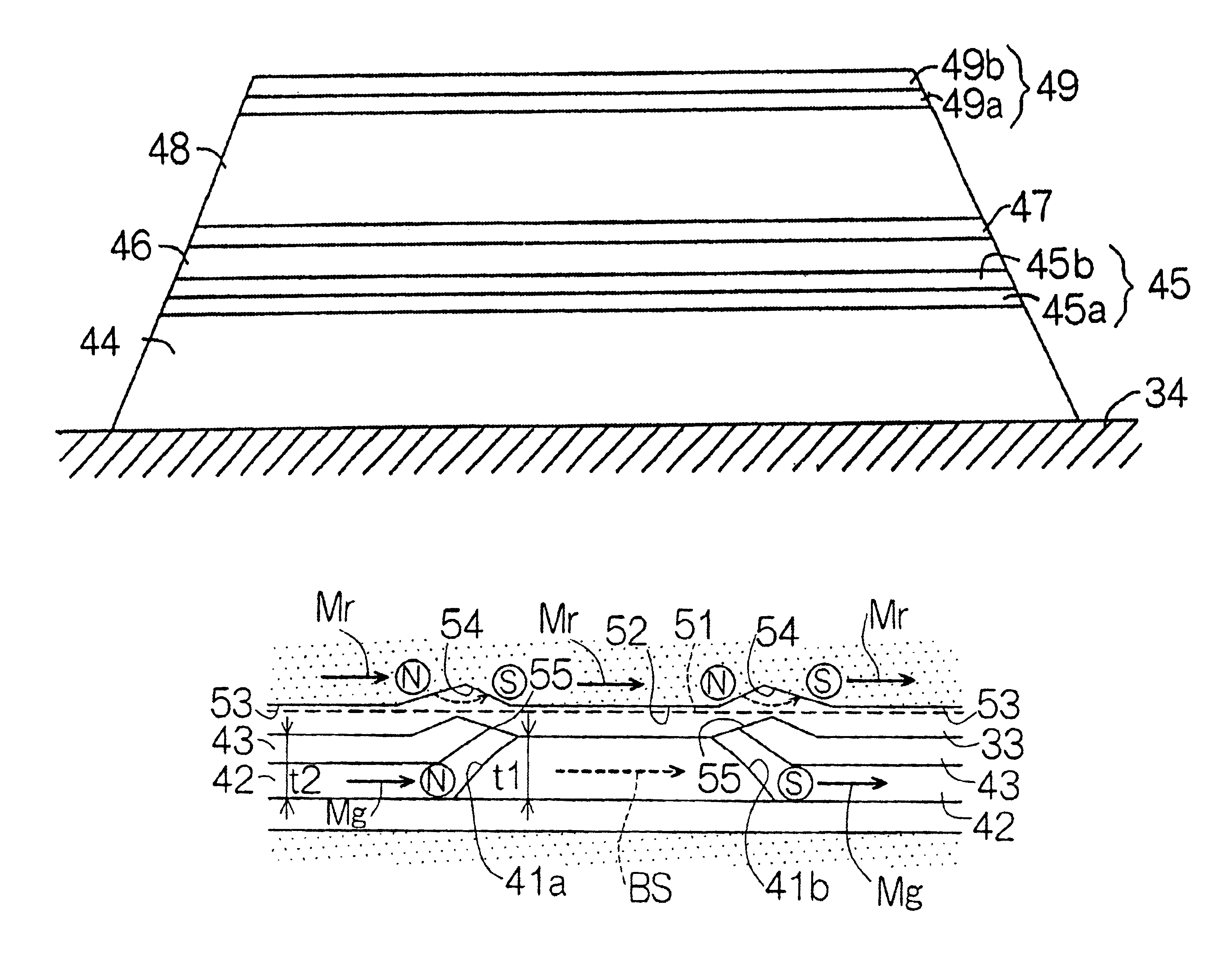
[0035]FIG. 12 is an enlarged partial front view of the read / write electromagnetic transducer for illustrating the process of magnetizing the domain control stripe layers in the MR element of the third embodiment;

[0036]FIG. 13 is an enlarged partial front view of the read / write electromagnetic transducer for illustrating the process of magnetizing the upper shield layer in the MR element of the third embodiment;

[0037]FIG. 14A illustrates a profile for the line of induction in the MR element of the third embodiment; and

[0038]FIG. 14B illustrates a profile for the magnitude of the magnetic field in the MR element of the third embodiment.

DESCRIPTION OF THE PREFERRED EMBODIMENTS

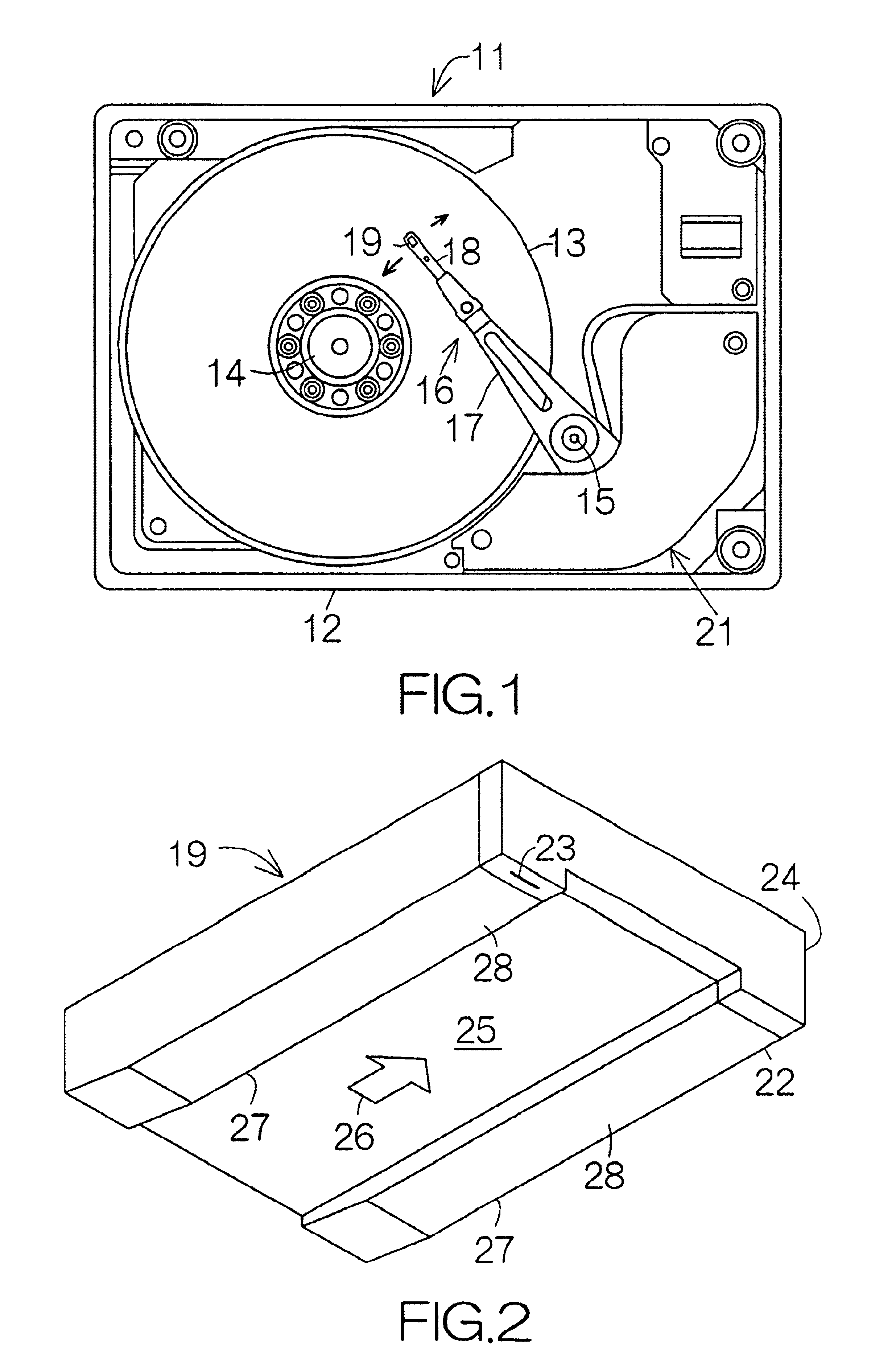
[0039]FIG. 1 schematically illustrates the interior structure of a hard disk drive (HDD) 11 as an example of a magnetic recording medium drive or storage device. The HDD 11 in...


PUM


Abstract

A magnetoresistive transducer includes a magnetoresistive (MR) film interposed between domain control layers along the surface of a lower non-magnetic gap layer. Lead layers are formed on the domain control layers. An upper non-magnetic gap layer and an upper shield layer are sequentially formed to extend over the MR film and the lead layers. The upper shield layer is opposed to the surfaces of the MR element and the lead layers at a flat boundary or interface. The residual magnetization is supposed to exist in the upper shield layer in the direction of the magnetization established in the domain control layers after the upper shield layer has been subjected to the applied magnetic field for the magnetization of the domain control layers. The residual magnetization can be kept continuous along the flat interface of the upper shield layer. Any magnetic poles are hardly generated along the interface of the upper shield layer. The longitudinal bias field can be prevented from receiving the interaction of the residual magnetization in the upper shield layer. Reduction in the longitudinal bias field can thus be suppressed.

Description

BACKGROUND OF THE INVENTION[0002]1. Field of the Invention[0003]The present invention relates to a magnetoresistive transducer in general employed in a magnetic recording medium drive or storage device such as a magnetic disk drive and a magnetic tape drive. In particular, the invention relates to a magnetoresistive transducer including a magnetoresistive film extending over the surface of a fundamental layer such as a non-magnetic layer spreading over a lower shield layer, and a pair of domain control layers extending over the surface of the fundamental layer so as to interpose the magnetoresistive film along the fundamental layer.[0004]2. Description of the Prior Art[0005]A well-known magnetoresistive transducer is sometimes designed to include a spin valve magnetoresistive (MR) film, for example. The spin valve MR film allows the magnetization to rotate in a constitutive free ferromagnetic layer in response to the reversal of the magnetic polarity applied from the outside, as con...

Claims


Application Information

Patent Timeline
IPC IPC(8): G01R33/06G01R33/09H01F10/00G11B5/39H01F10/32G11B5/31H01L43/08
CPCB82Y25/00G01R33/093H01L43/08G11B5/3903H01F10/3268G11B5/3113H10N50/10
Inventor TAGAWA, IKUYAYAMADA, KENICHIRO
Owner FUJITSU LTD
Why Eureka
Try Eureka