Automatic combustion control for a gas turbine

Inactive Publication Date: 2005-04-12
SIEMENS ENERGY INC
View PDF18 Cites 42 Cited by
  • Summary
  • Abstract
  • Description
  • Claims
  • Application Information

AI Technical Summary

Benefits of technology

Thus, it is desired to have a gas turbine control system and a method of operating a gas turbine engine that will ensure

Problems solved by technology

One method of limiting the production of nitrogen oxides is the use of a lean mixture of fuel and combustion air, i.e. a relatively low fuel-to-air ratio, thereby limiting the peak combustion temperature to a degree that reduces the production of NOx.
If these pressure pulses become excessive, mechanical damage can result in the turbine combustor and downstream components.
This approach, however, will exacerbate the problem of controlling NOx produ

Method used


Image

  • Automatic combustion control for a gas turbine
  • Automatic combustion control for a gas turbine
  • Automatic combustion control for a gas turbine

Examples


Embodiment Construction

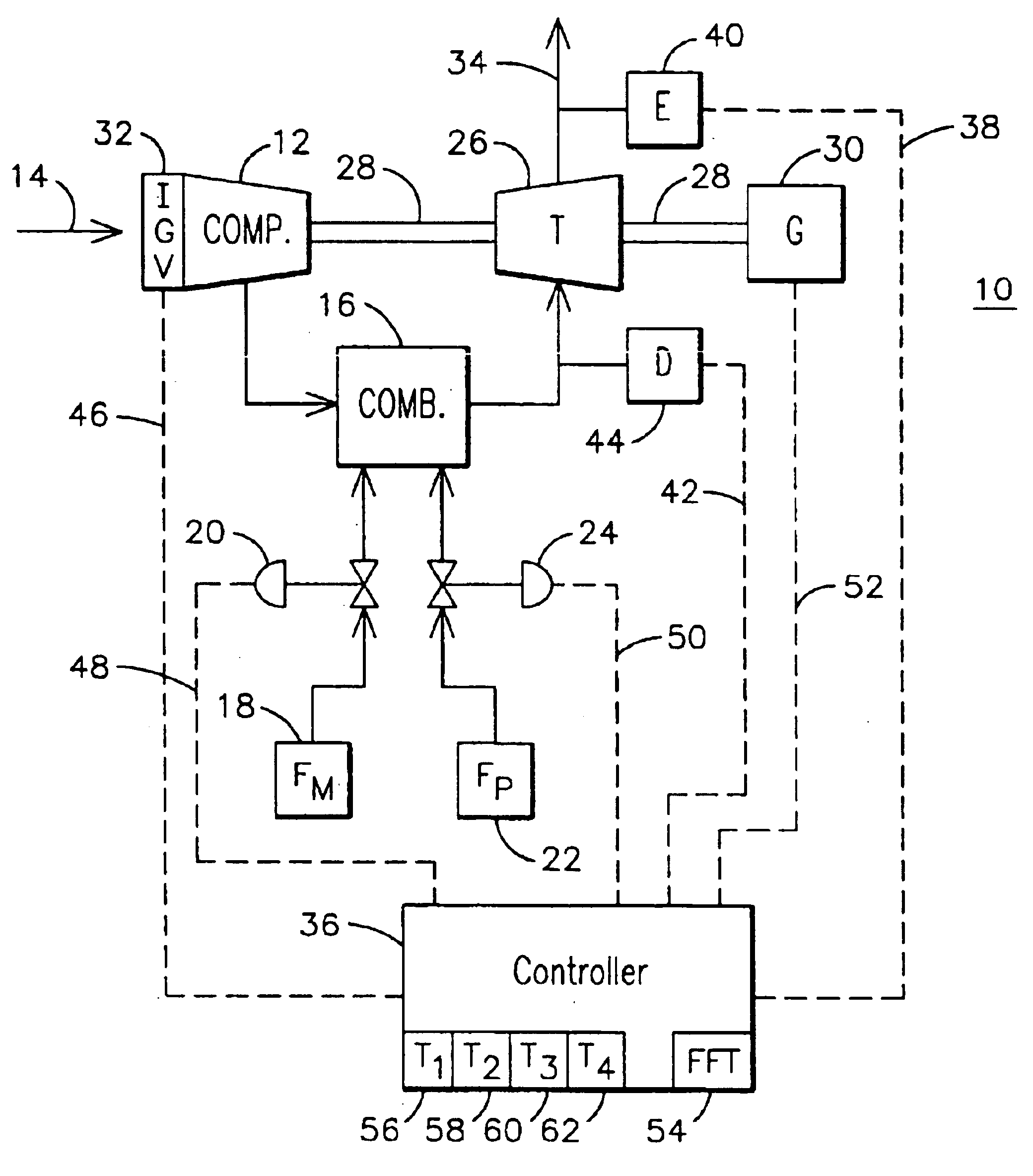
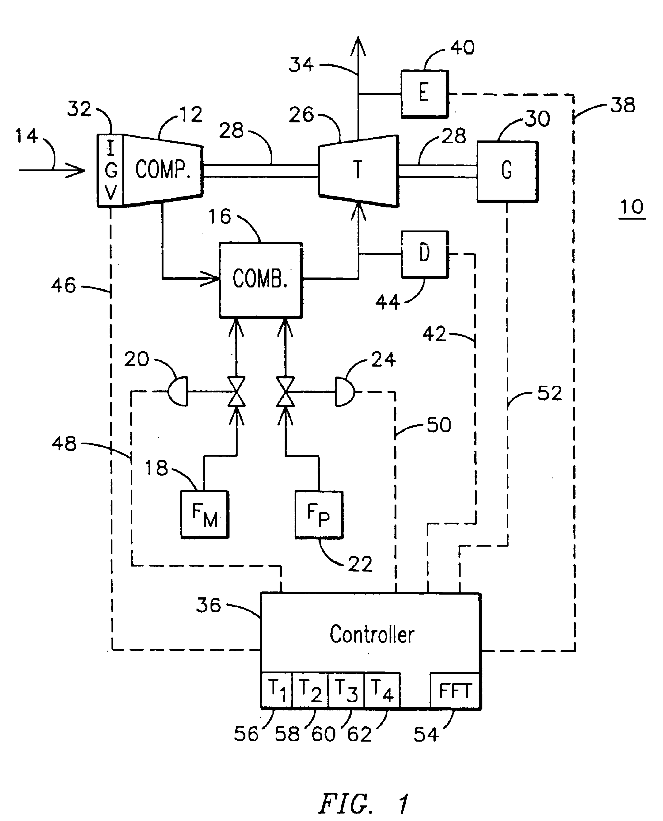
The gas turbine power generation system 10 illustrated in FIG. 1 includes a compressor 12 for receiving ambient air 14 and for providing compressed air to a combustor 16. The combustor 16 also receives combustible fuel, in this embodiment from a main fuel supply 18 through a main fuel supply throttle valve 20 and from a pilot fuel supply 22 through a pilot fuel supply throttle valve 24. The two fuel flows are directed to one or more pilot burners and C-stage burners in any low-NOx combustor design known in the art. The combustion of the combustible fuel in the compressed air results in the supply of hot combustion gas to turbine 26, where the hot combustion gas is expanded to recover energy in the form of the rotation of shaft 28 that is used, in turn, to drive the compressor 12 and an electrical generator 30. The inlet air is delivered to the compressor 12 through inlet guide vanes 32, and the turbine exhaust 34 is delivered back to the ambient atmosphere.

The system 10 is provided ...


PUM


Abstract

A method of controlling a gas turbine engine to provide protection against damaging pressure transients in the combustion process and to ensure compliance with emission requirements. Pressure fluctuations are monitored in a plurality of frequency ranges, and unacceptable pressure transients in different frequency ranges trigger different corrective actions. Unacceptable pressure transients in low and intermediate frequency ranges trigger a change in the pilot fuel fraction of a dual-mode combustor, while unacceptable pressure transients in a high frequency range trigger immediate power reduction in the engine. A control system for a gas turbine engine includes a plurality of timers for defining consecutive time periods for alternate monitoring of pressure transients and not monitoring pressure transients. Corrective action is taken only if unacceptable pressure transients are detected in each of the monitored time periods. As the combustion process is slowly adjusted to optimize emissions, the system will respond rapidly to an indication of an unacceptable dynamic condition.

Description

FIELD OF THE INVENTIONThis invention relates generally to the field of gas turbine engines, and more particularly to a system and method for controlling the combustion process of a gas turbine engine.BACKGROUND OF THE INVENTIONGas (combustion) turbine engines are used for generating power in a variety of applications including land-based electrical power generating plants. Gas turbines may be designed to combust a broad range of hydrocarbon fuels, such as natural gas, kerosene, biomass gas, etc. Gas turbines are known to produce an exhaust stream containing a number of combustion products. Many of these byproducts of the combustion process are considered atmospheric pollutants, and increasingly stringent regulations have been imposed on the operation of gas turbine power plants in an effort to minimize the production of these gasses. Of particular concern is the regulation of the production of the various forms of nitrogen oxides collectively known as NOx. It is known that NOx emiss...

Claims


Application Information

Patent Timeline
IPC IPC(8): F02C9/28F02C9/00
CPCF02C9/28F23R2900/00013F23N2900/05003
Inventor RYAN, WILLIAM RICHARDBERKSOY, SANEM
Owner SIEMENS ENERGY INC
Why Eureka
Try Eureka