Burner with low NOx emissions

Inactive Publication Date: 2005-04-12
EXXONMOBIL CHEM PAT INC
View PDF83 Cites 56 Cited by
  • Summary
  • Abstract
  • Description
  • Claims
  • Application Information

AI Technical Summary

Benefits of technology

Another object of the present invention is to provide an improved burner wherein localized sources of NOx production are substantially reduced

Problems solved by technology

However, increasingly stringent environmental regulations have shifted the focus of burner design to the minimization of regulated pollutants.
However, the reaction takes time and a mixture of nitrogen and oxygen at a given temperature for a very short time may produce less NOx than the same mixture at a lower temperature, over a longer period of time.
This strategy, known as Selective Catalytic Reduction (SCR), is very costly and, although it can be effective in meeting more stringent regulations, represents a less desirable alternative to improvements in burner design.
In addition, many raw gas burners produce luminous flames.
Since ethylene furnaces are amongst the highest temperature furnaces used in the hydrocarbon processing industry, the natural tendency of burners in these furnaces is to produce high levels of NOx emissions.
In addition, the fuel nozzles of such burners are generally exposed to the high temperature flue-gas in the firebox.
In the high temperature environment of steam-cracking furnaces used for the manufacture of ethylene, the combination of small diameter fuel nozzles and exposure to high temperature flue gas can lead to fouling and potential plugging of the fuel jets.
This not only has an adverse impact on burner performance, but also increases the cost of maintenance associated with repeated cleaning of fuel nozzles.
However this must be balanced with the fact that radiant heat transfer decreases with reduced flame temperature, while CO emissions, an indication of incomplete combustion, may actually increase.
A drawback of the system of U.S. Pat. No. 5,092,761 is that the staged-air used to cool the FGR duct must first enter the furnace firebox, traverse a short distance across the floor and then enter the FGR duct.
From the standpoint of NOx production, another drawback associated with the b

Method used


Image

  • Burner with low NOx emissions
  • Burner with low NOx emissions
  • Burner with low NOx emissions

Examples


example 1

To demonstrate the benefits of the present invention, a pair of pre-mix burners of the type described in U.S. Pat. No. 5,092,761 (as depicted in FIG. 5 of U.S. Pat. No. 5,092,761) were operated at a firing rate of 6 MMBTU / hr per burner, using a fuel gas comprised of 30% H2 / 70% natural gas, without steam injection. During this test, NOx emissions were measured at 88 ppm.

Tests were repeated with steam injection. Steam was injected, per burner, at 133 lb / hr and 195 lb / hr, with NOx emission levels measured at 58 ppm and 49 ppm, respectively.

example 2

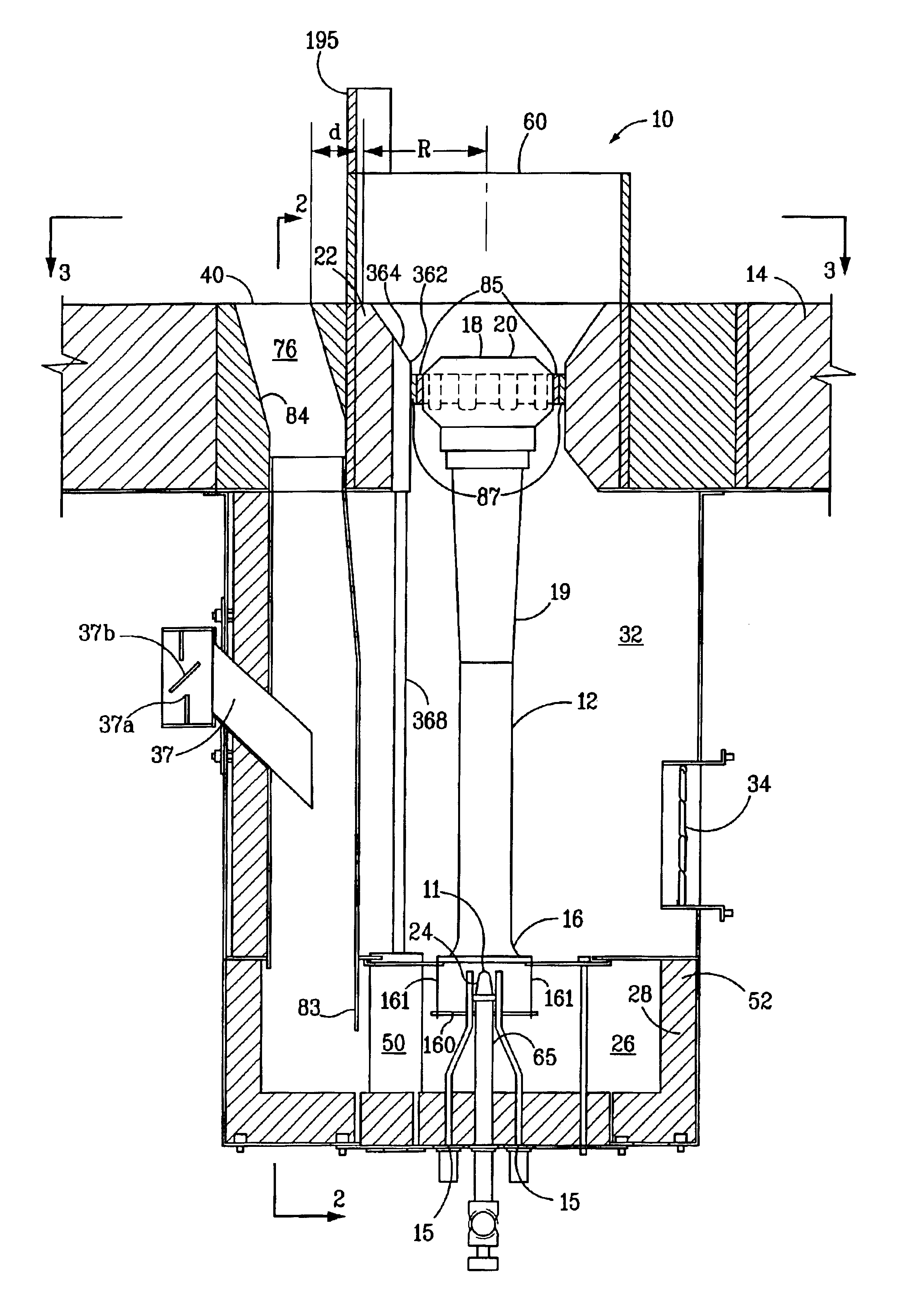
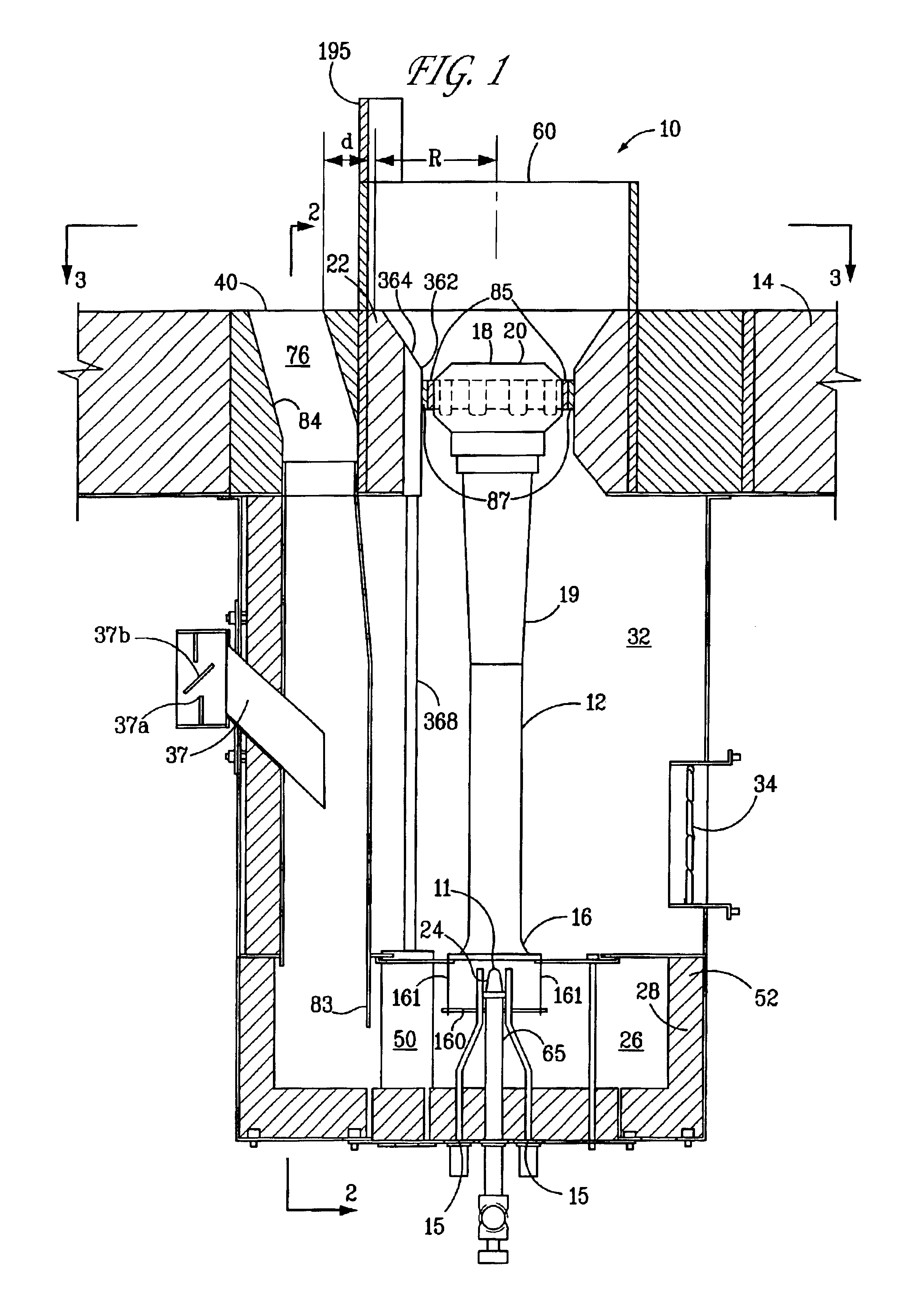
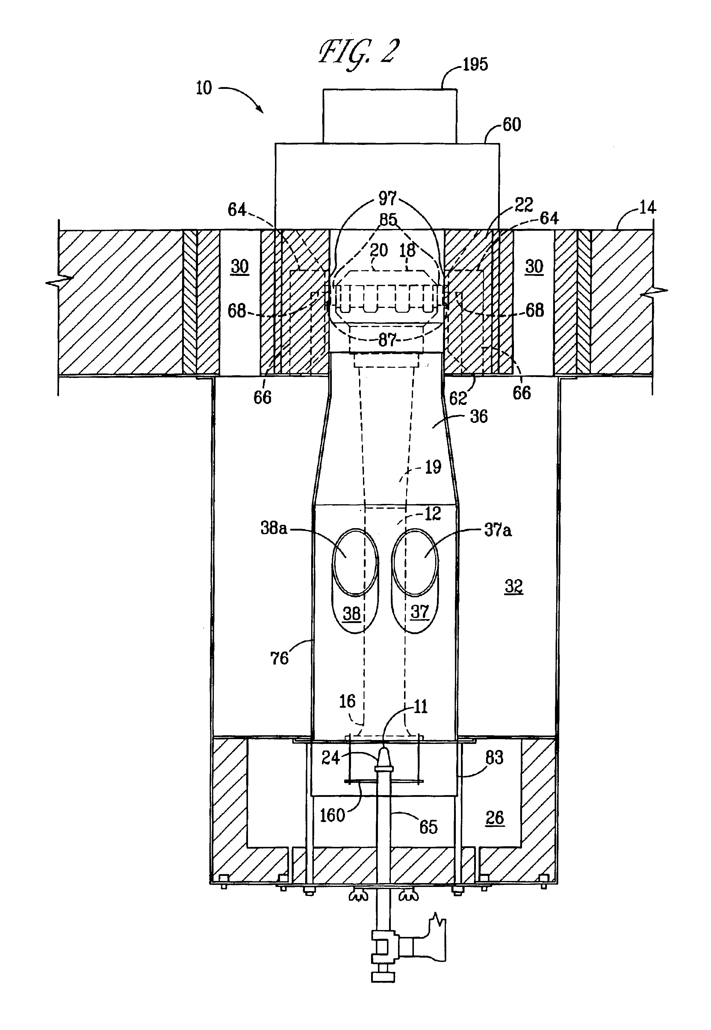
In this example, a pair of pre-mix burners employing the features depicted in FIGS, 1-5, 6B, 7B, 9A, 10B, and 12A were tested. The burner employed flue gas recirculation and was operated at a firing rate of 6 MMBTU / hr per burner, using a fuel gas comprised of 30% H2 / 70% natural gas, without steam injection. During this test, NOx emissions were measured at 42 ppm. Very stable flames were observed.

Tests were repeated with steam injection. Steam was injected, per burner, at 133 lb / hr, 195 lb / hr and 292 lb / hr, with NOx emission levels measured at 28.5 ppm, 23.5 ppm and 21 ppm, respectively. Once again, very stable flames were observed in each instance.

Although the burners of this invention have been described in connection with floor-fired hydrocarbon cracking furnaces, they may also be used in furnaces for carrying out other reactions or functions.

It will also be understood that the teachings described herein also have utility in traditional raw gas burners and raw gas burners having a...


PUM


Abstract

A burner for use in furnaces such as in steam cracking. The burner includes a primary air chamber; a burner tube having an upstream end, a downstream end and a venturi intermediate said upstream and downstream ends, said venturi including a throat portion having substantially constant internal cross-sectional dimensions such that the ratio of the length to maximum internal cross-sectional dimension of said throat portion is at least 3; a burner tip mounted on the downstream end of said burner tube adjacent a first opening in the furnace, so that combustion of the fuel takes place downstream of said burner tip; and a fuel orifice located adjacent the upstream end of said burner tube, for introducing fuel into said burner tube.

Description

FIELD OF THE INVENTIONThis invention relates to an improvement in a burner such as those employed in high temperature furnaces in the steam cracking of hydrocarbons. More particularly, it relates to an improved burner capable of increased flue gas recirculation, reduction in localized sources of NOx production, lower FGR duct temperatures and a resulting reduction in NOx emissions without an accompanying reduction in burner stability.BACKGROUND OF THE INVENTIONBecause of the interest in recent years to reduce the emission of pollutants from burners used in large furnaces and boilers, significant improvements have been made in burner design. In the past, improvements in burner design were aimed primarily at improving heat distribution. However, increasingly stringent environmental regulations have shifted the focus of burner design to the minimization of regulated pollutants.Oxides of nitrogen (NOx) are formed in air at high temperatures. These compounds include, but are not limited ...

Claims


Application Information

Patent Timeline
IPC IPC(8): F23M11/04F23D14/04F23C9/00F23C6/04F23C6/00F23M11/00F23M5/00F23L7/00F23M5/02F23C7/00F23C9/08F23C99/00F23D14/08F23D14/12F23D14/66F23D14/68
CPCF23C6/045F23M11/042F23C9/00F23C9/08F23D14/04F23D14/08F23D14/125F23D14/66F23D14/68F23L7/005F23M5/025F23C7/008F23C2202/10F23C2900/06041F23D2207/00F23D2212/10F23D2900/00011Y02E20/34
Inventor STEPHENS, GEORGESPICER, DAVID B.TRIMBLE, ROBERTGAUBA, GAUTAMBURY, MARK E.
Owner EXXONMOBIL CHEM PAT INC
Why Eureka
Try Eureka