Microfluidic devices with thick-film electrochemical detection

Inactive Publication Date: 2005-04-12
ARROWHEAD CENT
View PDF15 Cites 218 Cited by
  • Summary
  • Abstract
  • Description
  • Claims
  • Application Information

AI Technical Summary

Benefits of technology

A primary advantage of the present invention is the ease of use and cost advantage resulting from use of thick-film electrochemical detection combination with microfluidic devices, including microfluidic reaction and separation.
Another advantage of the present invention is that the thick-film electrode may be fabricated by screen printing.
Other objects, advantages and novel features, and further scope of applicability of the present inv

Problems solved by technology

Yet, such detection requires a large and expensive supporting optical system, and is limited to analytes that fluoresce or are amenable to derivatization with a fluorophore.
The major challeng

Method used


Image

  • Microfluidic devices with thick-film electrochemical detection
  • Microfluidic devices with thick-film electrochemical detection
  • Microfluidic devices with thick-film electrochemical detection

Examples


example 1

Apparatus Construction

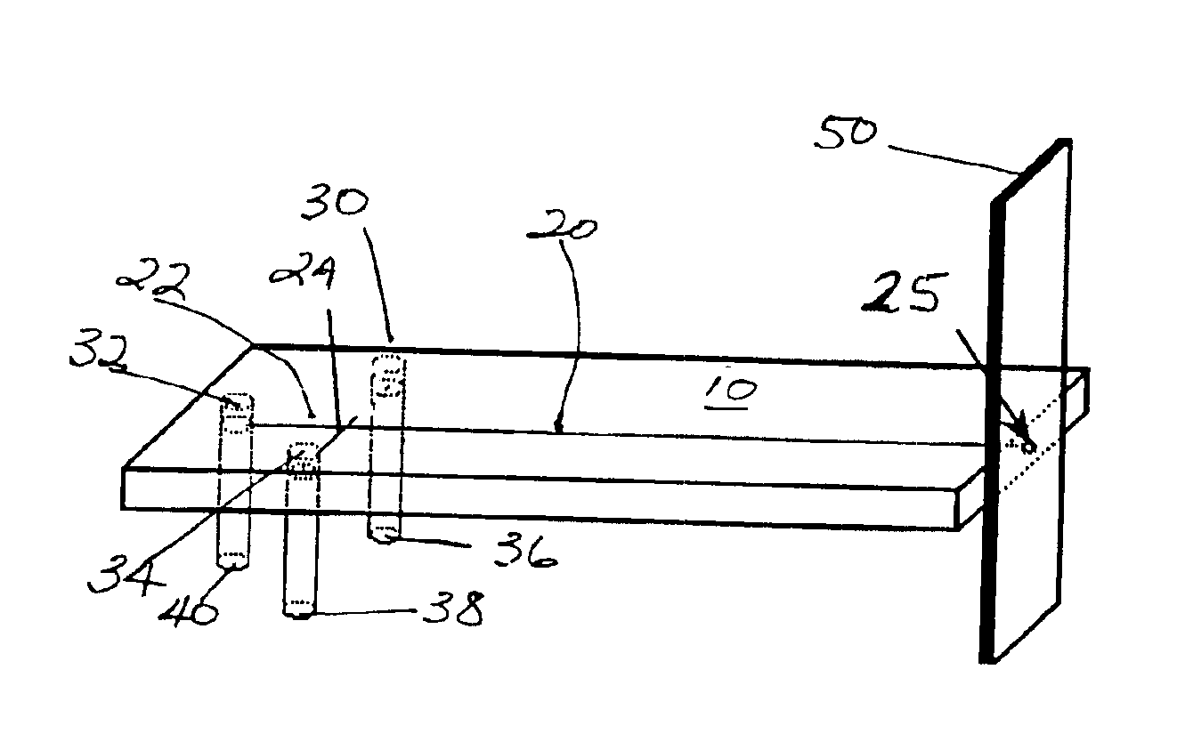
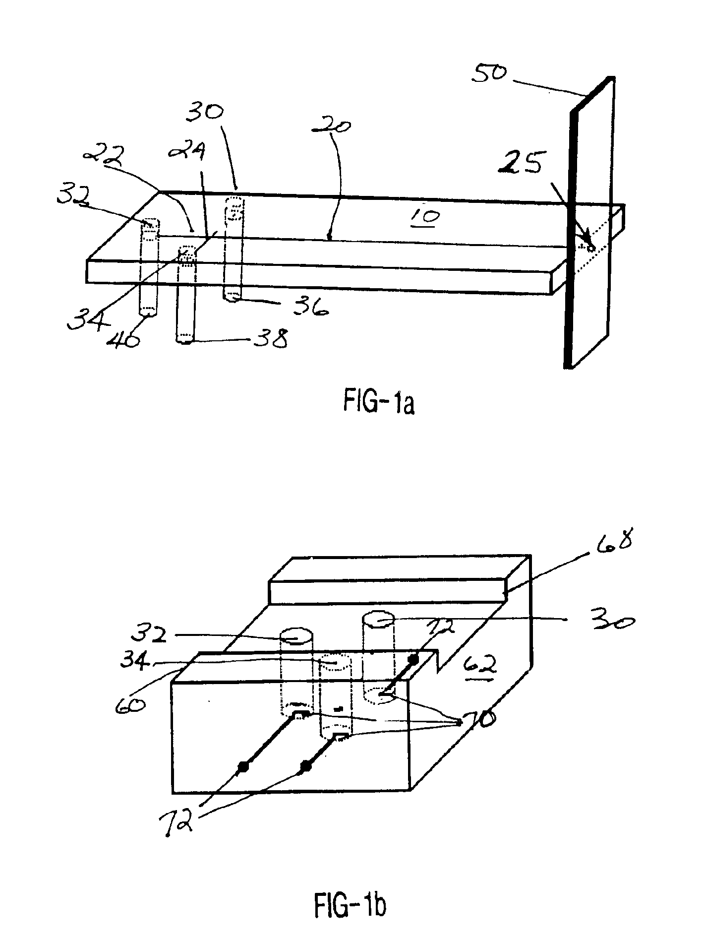
A high-voltage power supply with an adjustable voltage range between 0 and +4000 V was employed. Glass microchannel separation chips were fabricated at Alberta Microelectronic Corp. (AMC Model MC-BF4-001, Edmonton, Canada), using standard microphotolithographic technology, including wet chemical etching and thermal bonding techniques, as depicted in FIG. 1a. The resulting glass chip 10 consisted of a glass plate (120×87 mm), with a 77 mm long separation channel 20 located between a deliberately blocked and unused reservoir 32 and the channel outlet 24 at the detection reservoir 88, and a 10 mm long injection channel 24, located between the sample reservoir and the buffer reservoir. The two channels crossed each other halfway between the sample and the buffer reservoir and 5 mm from the blocked reservoir yielding a separation channel with an effective length of 72 mm. Each channel had a half-circle cross section, with a maximum depth of 20 μm and a width of 50 μ...

example 2

Screen-Printed Electrodes

Screen-printed electrodes were printed with a semi-automatic printer (Model TF 100, MPM, Franklin, Mass.). One of three different carbon inks were utilized for fabricating the working electrode, Acheson ink Electrodag 440B (49AB90) (Acheson Colloids, Ontario, CA), Ercon Ink G-448(I) (Ercon, Waltham, Mass.) and a ESL ink RS12113 modified to contain 30% extra carbon (Electro-Science Laboratories Inc., PA). Printing was performed through patterned stencils (100 μm thick, Specialty Photo-Etch, Inc., Texas) onto 100×100×0.64 mm alumina ceramic plates. Each plate consisted of 30 strips (33.3×10.0×0.64 mm) with each strip being defined by a laser pre / semi cut. The total printing procedure consisted of the following steps. A carbon ink working-electrode layer (0.3×8.0 mm) was first printed on each of the strips of the ceramic plate and was cured at 100° C. for 30 minutes. Then, a silver Ink (Ercon R-421 (DRE-68)) contact layer (1.5×21.0 mm), partially overlapping th...

example 3

Electrophoresis Procedure for Catecholamines and Nitroaromatic Explosives

Prior to use, the channels of the CE chip of Example 1 were treated by rinsing with a 1.0 M sodium hydroxide solution for 20 minutes, followed by deionized water for 1 minute, 1.0% hydrochloric acid for 20 minutes, and finally with deionized water for 1 minute. For the separation, the buffer and sample reservoirs in the chip holder and the corresponding pipette tips on the micro-channel chip were filled with 250 μl buffer and sample solutions, respectively. The chip was then placed in its holder with the pipette tips pointing downwards into the reservoirs and the detection reservoir was filled with buffer solution. Finally, the high voltage power supply was connected to the reservoirs. In order to fill the injection channel between the separation channel and the sample reservoir with sample solution, +1500 V was applied for 30 seconds to the sample reservoir with the detection reservoir grounded and the buffer ...


PUM

PropertyMeasurementUnit
Thicknessaaaaaaaaaa
Thicknessaaaaaaaaaa
Thicknessaaaaaaaaaa

Abstract

An apparatus for conducting a microfluidic process and analysis, including at least one elongated microfluidic channel, fluidic transport means for transport of fluids through the microfluidic channel, and at least one thick-film electrode in fluidic connection with the outlet end of the microfluidic channel. The present invention includes an integrated on-chip combination reaction, separation and thick-film electrochemical detection microsystem, for use in detection of a wide range of analytes, and methods for the use thereof.

Description

COPYRIGHTED MATERIALA portion of the disclosure of this patent document contains material that is subject to copyright protection. The owner has no objection to the facsimile reproduction by anyone of the patent document or the patent disclosure, as it appears in the Patent and Trademark Office patent file or records, but otherwise reserves all copyrights whatsoever.BACKGROUND OF THE INVENTION1. Field of the Invention (Technical Field)The present invention relates to electrochemical detection of analytes using thick-film electrodes, including screen-printed thick-film electrodes, in microfluidic devices, including separation devices such as capillary electrophoresis microsystems.2. Background ArtNote that the following discussion refers to a number of publications by author(s) and year of publication, and that due to recent publication dates certain publications are not to be considered as prior art vis-a-vis the present invention. Discussion of such publications herein is given for...

Claims


Application Information

Patent Timeline
IPC IPC(8): G01N27/447
CPCG01N27/44791G01N27/4473
Inventor WANG, JOSEPHTIAN, BAOMINSAHLIN, ESKIL
Owner ARROWHEAD CENT
Why Eureka
Try Eureka