
Plasma display panel and fabrication method of the same

a technology of plasma and display panels, which is applied in the manufacture of electrodes, electrode systems, electric discharge tubes/lamps, etc., can solve the problems of difficult uniform reset of sustaining discharge by a low priming voltage, meaningless evaluation of priming voltage by conventional evaluation methods of mgo protection films, etc., to achieve the effect of improving contrast and lowering priming voltag

Inactive Publication Date: 2005-04-12
PANASONIC CORP
View PDF5 Cites 18 Cited by
  • Summary
  • Abstract
  • Description
  • Claims
  • Application Information

AI Technical Summary

Benefits of technology

Another object of the present invention is to provide a plasma display panel having a protection film for lowering the priming voltage, which is capable of driving with low priming voltage and of performing a high contrast display without erroneous lightening or flicker by performing a uniform resetting of the panel with the low priming voltage.
The present invention is featured by that an increase of impurity in a protection film (MgO film) is restricted to, for example, 400 ppm or less, by forming the protection film with a highly pure film material in a hydrogen ion environment. With such feature of the present invention, it is possible to lower the priming voltage in driving a PDP after aged to thereby improve the contrast of display thereof.

Problems solved by technology

Therefore, the conventional evaluation method of the MgO protection film is meaningless in evaluating the priming voltage of the practical PDP.
Accordingly, it is impossible to obtain a MgO protection film having a low priming voltage by merely defining the metal ion density of the deposition material of the MgO protection film.
Furthermore, although, in evaluating the drive characteristics of a PDP, it is necessary to once reset a sustaining discharge of the whole area of the PDP by a priming discharge, to lighten the whole area and then to darken the whole area by a priming erase, it is difficult to uniformly reset the sustaining discharge by a low priming voltage since the priming voltage of the conventional protection film is high.
If the uniform resetting of the sustaining discharge is impossible, there may be erroneous lightening or flicker.
Therefore, there may be cases where the sputtering durability characteristics of the MgO protection film becomes insufficient.

Method used


Image

  • Plasma display panel and fabrication method of the same
  • Plasma display panel and fabrication method of the same
  • Plasma display panel and fabrication method of the same

Examples


Embodiment Construction

Embodiments of the present invention will be described in detail with reference to the drawings.

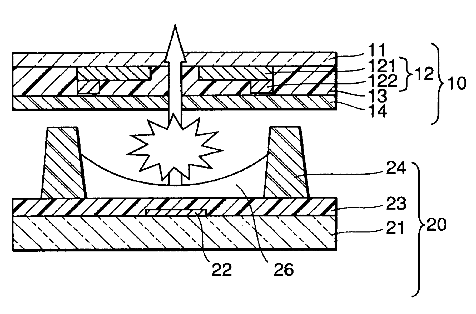
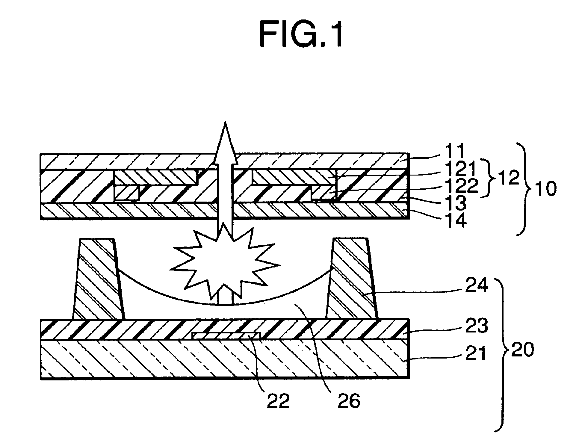
FIG. 1 is a cross section of a light-emitting cell, which is a basic unit pixel of an AC type color PDP according to the present invention. As shown in FIG. 1, the PDP has a front substrate 10 and a rear substrate 20 arranged in parallel to the front substrate 10 with a predetermined gap.

The front substrate 10 is composed of a glass substrate 11 and a discharge-sustaining electrode 12 provided on the glass substrate 11. The discharge-sustaining electrode 12 includes a transparent electrode 121 and a bus electrode 122 in the form of a metal film and is covered by a transparent dielectric layer 13 for AC drive. A protection film 14 in the form of a MgO film 1 μm thick is formed on a surface of the dielectric layer 13.

On the other hand, the rear substrate 20 is composed of a glass substrate 21 and an address electrode 22 provided on the glass substrate 21. An underlying layer 23 formed of a ...


PUM

PropertyMeasurementUnit
conductivityaaaaaaaaaa
temperatureaaaaaaaaaa

Abstract

A protection film for protecting a dielectric layer of an AC type PDP is formed such that impurity metal ion densities of the protection film of the PDP, which is aged, become 400 ppm or less, respectively, and the protection film contains three or more hydrogen atoms assuming that the total number of atoms of the protection film is 100.

Description

BACKGROUND OF THE INVENTION1. Field of the InventionThe present invention relates to a plasma display panel (PDP) having a protection film for protecting a dielectric layer of the PDP from discharge and a fabrication method of the same plasma display panel and, particularly, the present invention relates to a plasma display panel having a magnesium oxide (MgO) protection film for improving discharge characteristics of the plasma display panel and a fabrication method of the same.2. Description of the Prior ArtIn general, the plasma display panel (PDP) is featured by thin structure, flicker-free display, high display contrast ratio, possibility of providing a relatively large display screen, short response time and self-light emission type with which a multi-color display can be realized by using various phosphor materials, etc. Therefore, the PDP is becoming popular in the field of color image display, which is related to computers.The PDP is classified to an AC type PDP and a DC ty...

Claims


Application Information

Patent Timeline
Patent Type & Authority Patents(United States)
IPC IPC(8): H01J17/49H01J9/02C23C14/08H01J11/12H01J11/22H01J11/24H01J11/26H01J11/34H01J11/40
CPCH01J9/02H01J11/40H01J11/12H01J11/38
Inventor HIRANO, TOSHIAKIITOH, KEN
Owner PANASONIC CORP
Learn More