Batch furnace

a technology of micro-flue furnaces and batch furnaces, which is applied in the direction of muffler furnaces, furnaces, applications, etc., can solve the problems of difficult and inefficient to lower the temperature of the entire furnace assembly, ineffective convective heating, and time-consuming heating arrangements, etc., and achieves rapid ramp-up and ramp-down times and small thermal mass

Inactive Publication Date: 2005-04-12
WAFERMASTERS
View PDF6 Cites 13 Cited by
  • Summary
  • Abstract
  • Description
  • Claims
  • Application Information

AI Technical Summary

Benefits of technology

Advantageously, heating and cooling of the wafers occurs internal to the process chamber using a convective type of heating. The heat transfer between the circulating heated gas and the wafers is more direct than using radiation or other forms of conduction heating arrangements. Because the wafers are cooled within the process chamber, a separate cooling chamber or blower is not required. Since the heating element has a small thermal mass, rapid ramp-up and ramp-down times are achievable.

Problems solved by technology

Unfortunately, it has been found that in most conventional vertically arranged furnaces, the desired temperature is obtained in the process tube by surrounding the tube with heating elements.
Convective heating is usually not effective because the process tube is typically isolated.
During low temperature wafer processing operations, this type of heating arrangement is usually very inefficient and time consuming.
Further, in this type of arrangement, a separate cooling chamber or blower for fast cooling of the entire furnace, is typically required since, it is difficult and inefficient to lower the temperature of the entire furnace assembly between processing operations on different batches of wafers.

Method used


Image

  • Batch furnace
  • Batch furnace
  • Batch furnace

Examples


Embodiment Construction

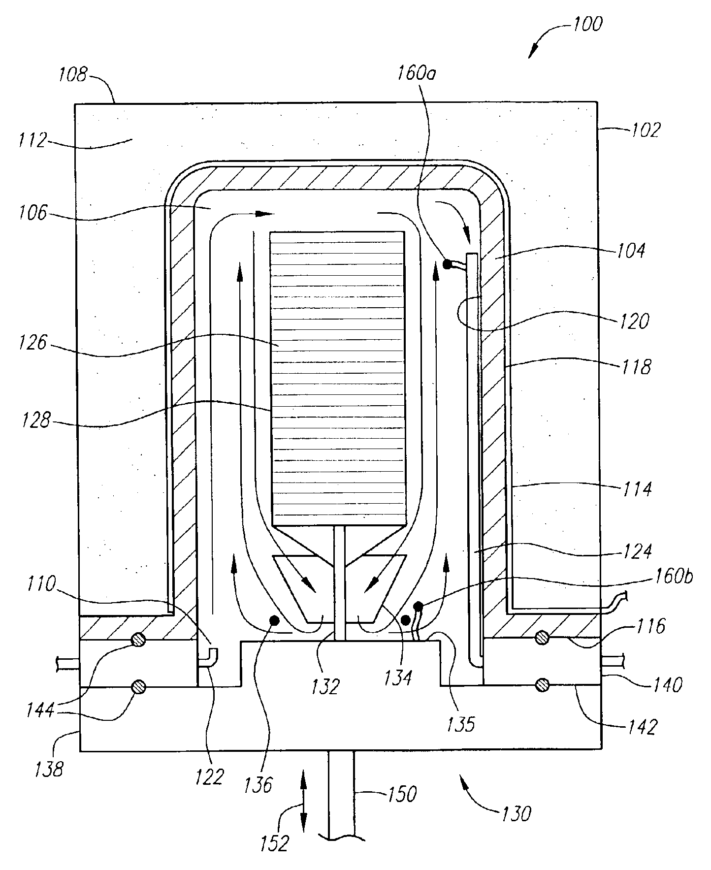
FIG. 1 is a simplified cross-sectional view of one embodiment of the furnace assembly 100 of the present invention. Furnace assembly 100 includes a process chamber 102 enclosing process tube 104, which defines an internal space 106.

Externally, in one embodiment, process chamber 102 may include a metallic housing 108, preferably made of aluminum, stainless steel, or similar metal. Within housing 108, between housing 108 and process tube 104, may be an internal thermal insulation material 112. Insulation material 112 helps to minimize heat loss from process tube 104 through housing 108 to the outside environment. Optionally, a heating element 114 may be disposed between process tube 104 and insulation layer 112 to increase the temperature around process tube 104, which further minimizes heat loss through housing 108 to the outside environment and to reduce time for the temperature within process tube 104 to stabilize. Insulation material 112 may be made of any suitable insulation mate...


PUM

PropertyMeasurementUnit
temperatureaaaaaaaaaa
internal pressuresaaaaaaaaaa

Abstract

A system and method for isothermally distributing a temperature across a semiconductor device. A furnace assembly is provided, which includes a processing tube configured to removably receive a wafer carrier having a full compliment of semiconductor wafers. A heating assembly is provided which can include a heating element positioned to heat air or other gases allowed to enter the process tube. The furnace assembly and process tube are capable of being vertically raised and lowered into a position enclosing the heating assembly within the process tube. Once the heating assembly forms a seal with the process tube, the process tube is exhausted and purged of air. Gas is then allowed to flow into the process tube and exchange heat with the heating element. The heated gas circulates through the process tube to convectively change the temperature of the wafers.

Description

BACKGROUND1. Field of the InventionThis invention generally relates to semiconductor manufacturing equipment and, more particularly, to a system and method used for the processing of semiconductor wafers.2. Description of the Related ArtDuring the processing of semiconductor devices, it is highly desirable to accurately control the thermal treatment to which the devices are exposed during processing. In some instances, batches of devices, primarily wafers, are processed in a semiconductor processing furnace, which has a carefully controlled processing environment to effect the desired processes.Unfortunately, it has been found that in most conventional vertically arranged furnaces, the desired temperature is obtained in the process tube by surrounding the tube with heating elements. In this arrangement radiation and convection are used to heat the process tube first, before the heat energy is transferred to the cooler wafers. Convective heating is usually not effective because the p...

Claims


Application Information

Patent Timeline
Patent Type & Authority Patents(United States)
IPC IPC(8): C23C16/46H01L21/00H01L21/205H01L21/26H01L21/324
CPCC23C16/46H01L21/67115H01L21/67109H01L21/324
Inventor YOO, WOO SIKFUKADA, TAKASHI
Owner WAFERMASTERS
Why Eureka
Try Eureka