Toroidal internal combustion engine

a technology of internal combustion engine and turbine engine, which is applied in the direction of liquid fuel engine, machine/engine, mechanical apparatus, etc., can solve the problems of frictional work, inherently inefficient transfer of work output from linear to rotational motion, and energy released by combustion, so as to reduce emissions, reduce frictional work, and improve work efficiency

Inactive Publication Date: 2005-04-19
APPLIED THERMAL SCI
View PDF20 Cites 34 Cited by
  • Summary
  • Abstract
  • Description
  • Claims
  • Application Information

AI Technical Summary

Benefits of technology

[0009]For the reasons given above, it is an object of the present invention to provide an IC engine that provides superior performance and reduced emissions. It is a further object to provide such an engine that has fewer moving parts, is lighter in weight, and small in size than a conventional IC engine of comparable power. It is a yet further object to provide such an engine in which the mechanical forces are dynamically balanced and the thermal stresses evenly distributed. It is a still further object to provide such an engine that requires fewer and simpler seals and has reduced requirements for cooling and lubrication.

Problems solved by technology

One major disadvantage is that the energy released by combustion is converted work via linearly moving pistons and is then converted to rotational work output when it is transmitted to the crankshaft.
This transfer of work output from linear to rotational motion is inherently inefficient for several reasons.
For one, the slider crank mechanism that receives the work output from the piston is not at an optimum position for producing high torque on the crankshaft when pressure in the combustion chamber peaks and, consequently, only a portion of the energy generated by the combustion process is transmitted to the crankshaft, with the rest being dissipated in side thrust resulting in frictional work.
The poppet valves typically used in the reciprocating IC engine are also sources of energy loss for several reasons.
First, they are subject to high friction, noise, and vibration, all of which dissipate energy.
The typical valve configuration, in which both intake and exhaust valves are located in close proximity to each other in the cylinder head, is also a source of energy loss during valve overlap.
Despite these advantages, problems of nonuniform heating, sealing, inertia effects, and / or lubrication have prevented these engines from taking hold in the market place.
However, due to the configuration and engine construction, the forces exerted on the rotors and, thus, the housing are very high and will necessarily require very high-performance seals, problems that the designs of these engines do not solve.
None of the disclosures for the toroidal engines of the prior art addresses cooling techniques to prevent overheating, warping, or destruction of the engine during routine operation.

Method used


Image

  • Toroidal internal combustion engine
  • Toroidal internal combustion engine
  • Toroidal internal combustion engine

Examples


Embodiment Construction

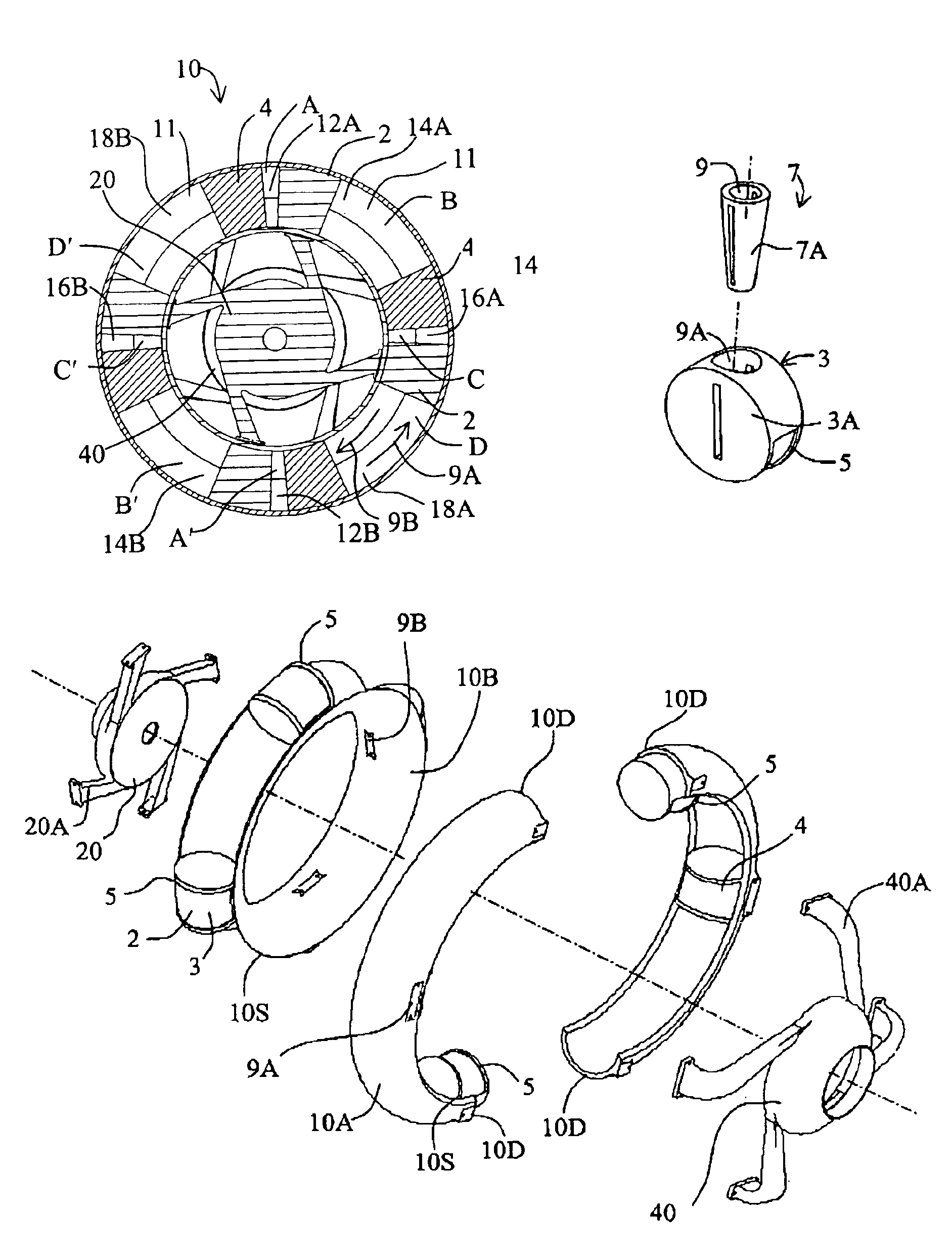
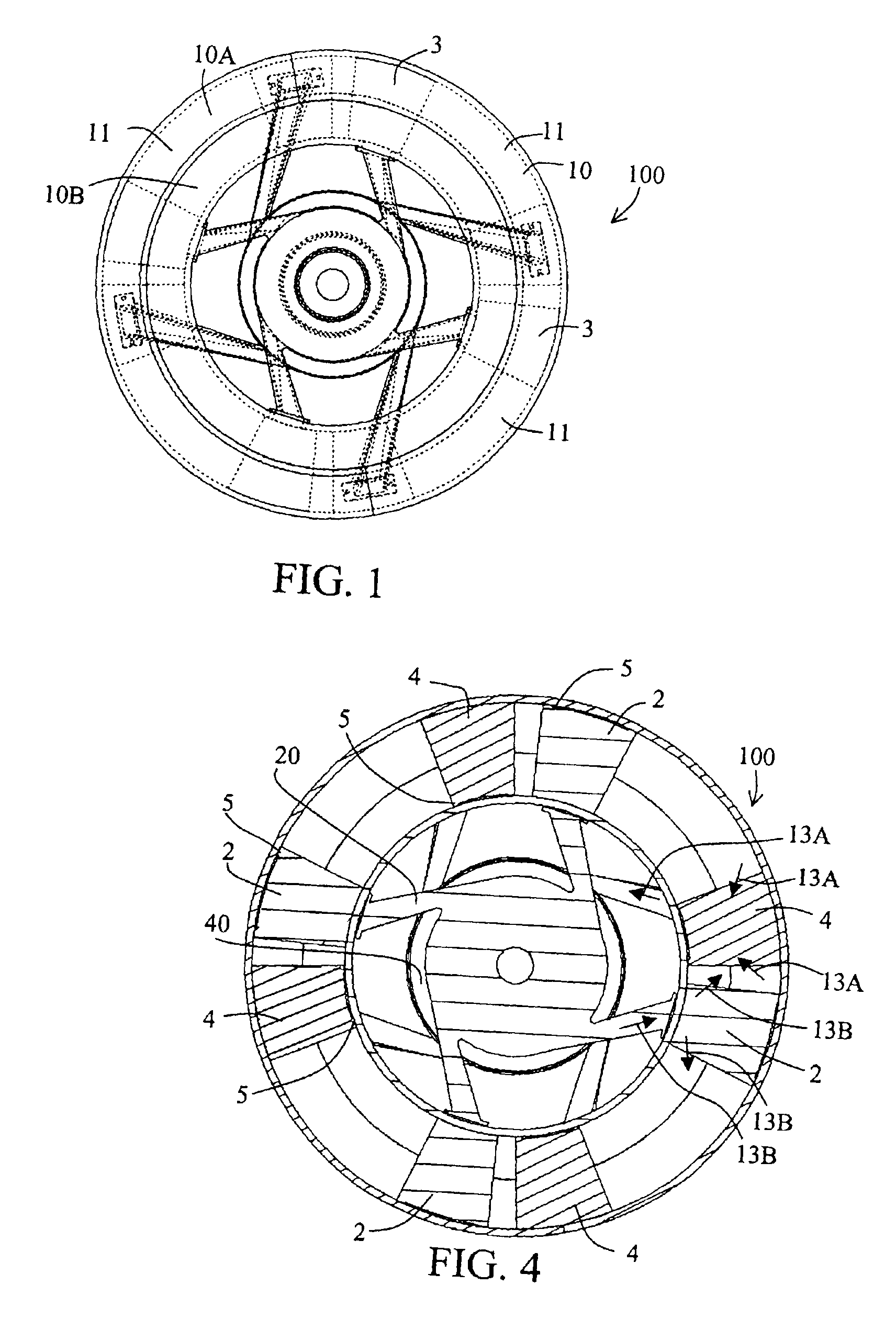
[0045]FIG. 1 is a schematic illustration of a toroidal IC engine 100 according to the invention. The toroidal IC engine 100 comprises an engine ring 10 with a plurality of pistons 3. For purposes of illustration and simplicity, the description of the toroidal IC engine 100 will be based on a four-stroke engine having eight pistons 3 and eight chambers 11. It should be understood, however, that the toroidal IC engine 100 is configurable as a two-stroke or a four-stroke engine, with any number of pistons greater than one, depending on the size and power requirements of the engine.

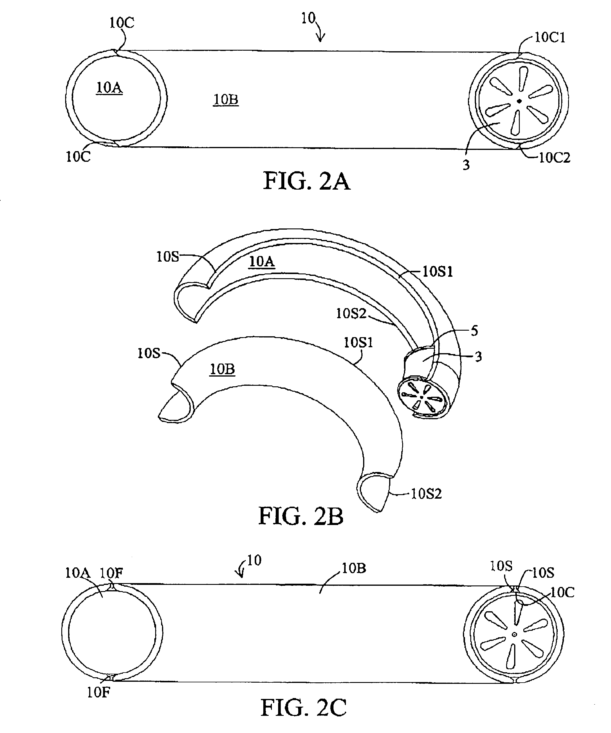
[0046]FIGS. 2A-2B illustrate the basic construction of the engine ring 10. The engine ring 10 is a split ring having an outer engine ring 10A and an inner engine ring 10B. As shown, both the inner and outer engine rings 10B, 10A are C-shaped and have seam edges 10S which include a first seam edge 10S1 and a second seam edge 10S2. The outer engine ring 10A and inner engine ring 10B are joined together along th...


PUM


Abstract

Toroidal internal combustion engine comprising two concentric engine rings. Intake valves are assembled in two faces of one set of pistons and exhaust valves in two faces of the second set of pistons. The intake-valve pistons are fixedly attached to one of the engine rings and the exhaust-valve pistons to the other engine ring. The face of one intake-valve piston and the face of one adjacent exhaust-valve piston form boundaries of an engine chamber. Combustion forces on the piston faces force the two concentric engine rings to counter-rotate. The intake-valve piston and the adjacent exhaust-valve piston sweep the same chamber volume at different strokes of the engine cycle. The engine is constructed of CRC material and mounted on a central shaft, with the intake manifold and the exhaust manifold mounted on each side of the engine, providing a lightweight, self-lubricating, highly fuel efficient, and dynamically balanced engine.

Description

BACKGROUND INFORMATION[0001]1. Field of the Invention[0002]The field of the invention relates to internal combustion (IC) engines. More particularly, the invention relates to toroidal internal combustion engines.[0003]2. Description of the Prior Art[0004]The traditional reciprocating IC engine has been around for more than 100 years, yet its design has several inherent disadvantages. One major disadvantage is that the energy released by combustion is converted work via linearly moving pistons and is then converted to rotational work output when it is transmitted to the crankshaft. This transfer of work output from linear to rotational motion is inherently inefficient for several reasons. For one, the slider crank mechanism that receives the work output from the piston is not at an optimum position for producing high torque on the crankshaft when pressure in the combustion chamber peaks and, consequently, only a portion of the energy generated by the combustion process is transmitted...

Claims


Application Information

Patent Timeline
Patent Type & Authority Patents(United States)
IPC IPC(8): F01C9/00F02B53/00
CPCF01C9/002F02B2730/03F02B53/00
Inventor HOOSE, KARL V.
Owner APPLIED THERMAL SCI
Why Eureka
Try Eureka