Solid electrolytic capacitors

a technology of solid electrolyte and capacitor, which is applied in the direction of fixed capacitor details, variable capacitors, fixed capacitors, etc., can solve the problems of self-generation of heat, prone to fumes or fires, and solid electrolyte layers are easy to produce fumes or ignition, etc., to achieve convenient fabrication, easy to handle, and easy to provide

Active Publication Date: 2005-04-19
TYCO ELECTRONICS RAYCHEM KK +2
View PDF9 Cites 16 Cited by
  • Summary
  • Abstract
  • Description
  • Claims
  • Application Information

AI Technical Summary

Benefits of technology

[0016]When the electrode members are each in the form of a plate or foil, the current control layer is easy to handle in the process for fabricating the capacitor, and becomes easy to provide on the anode side. Further when the current control mean is provided in the form of an element, i.e., as a current control element, the solid electrolytic capacitor becomes easy to fabricate. When the anode terminal member or cathode terminal member is made to partly serve as an electrode member, the capacitor can be constructed with a reduced number of components.
[0017]Preferably, the electrode members sandwiching the current control layer therebetween is made from at least one of nickel and copper. Further when the current control layer is made from a polyethylene resin having conductor particles admixed therewith, the layer exhibits a greatly increased resistance value at about 120° C. and higher temperatures, and is capable of controlling short-circuit current of the capacitor at a considerably lower temperature than the solid electrolytic capacitors having a conventional current control layer.

Problems solved by technology

When the anode and the cathode of such a solid electrolytic capacitor short-circuit, for example, due to a break of or damage to the dielectric coating layer 2, self-generation of heat occurs, possibly producing fumes or a fire in an extreme case.
Further when the conductive inorganic material contains oxygen, the solid electrolyte layer is prone to fuming or ignition.
It is therefore impossible to provide a fuse in solid electrolytic capacitors which are designed for reduced ESR, especially in those wherein a conductive polymer is used.
The fuse provided in solid electrolytic capacitors has another problem in that it is difficult to serve as a countermeasure against fuming and ignition due to a moderate rise in temperature although capable of serving such a function against instantaneous overcurrent.
The conventional current control layer for use in solid electrolytic capacitors as disclosed in the publication of JP-A No. 1997-129520 undergoes healing at a high temperature of over 300° C. and is therefore unsuitable for preventing fuming and ignition due to a moderate rise in temperature.
Furthermore, if the current control layer is formed directly between the cathode leading layer 4 and the cathode terminal member 62 in the process for fabricating the solid electrolytic capacitor, the process will then require a prolonged period of time and become more cumbersome.

Method used


Image

  • Solid electrolytic capacitors
  • Solid electrolytic capacitors
  • Solid electrolytic capacitors

Examples


first embodiment

(First Embodiment)

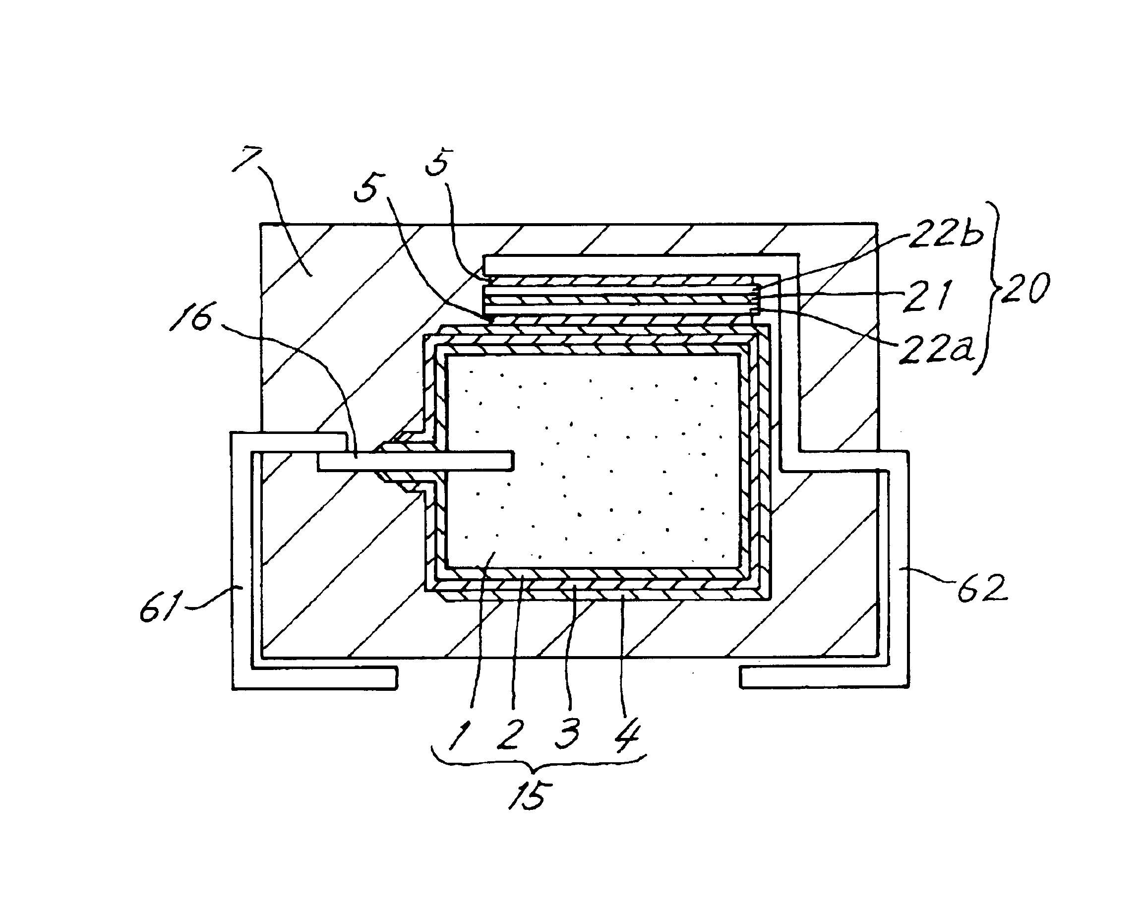
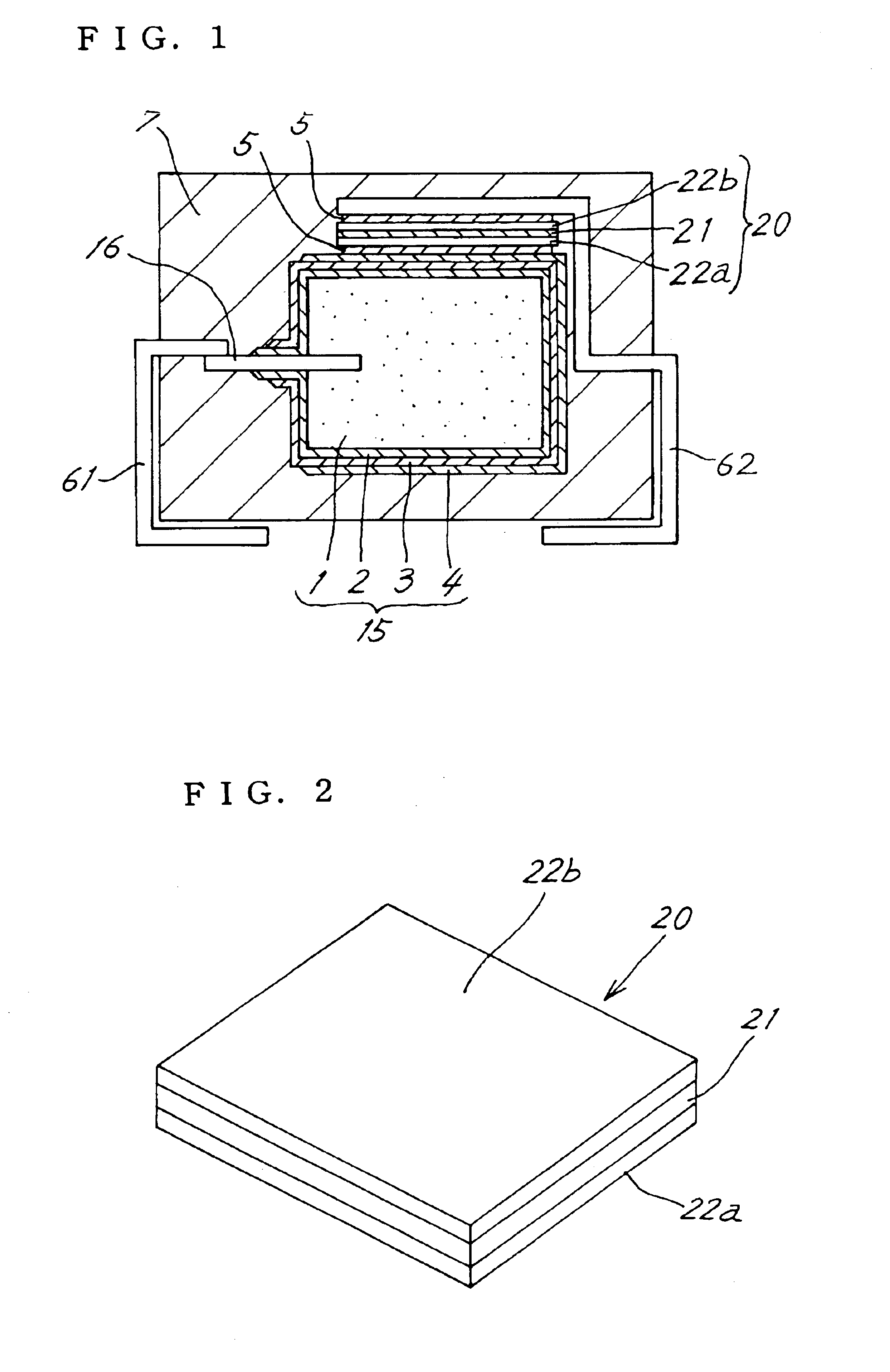
[0034]FIG. 1 is a view in vertical section of a solid electrolytic capacitor of first embodiment of the invention. A capacitor element 15 comprises an anode body 1 having an anode leading member 16 in the form of a rod and embedded in the body 1. The anode body 1 is a substantially rectangular parallelepipedal sintered body of valve metal. According to the present embodiment, a sintered body of tantalum is used as the anode body 1, whereas a sintered body of aluminum, niobium, titanium, zirconium or the like may alternatively be used. Further according to the present embodiment, a tantalum wire is used as the anode leading member 16.

[0035]The sintered body is immersed in an aqueous solution of H2PO4 and subjected to an anodic oxidation treatment, whereby a dielectric coating layer 2 is formed over the surface of the anode body 1. The anode body 1 resulting from the anodic treatment is subjected to a polymerization treatment to thereby form a solid electrolyte layer...

second embodiment

(Second Embodiment)

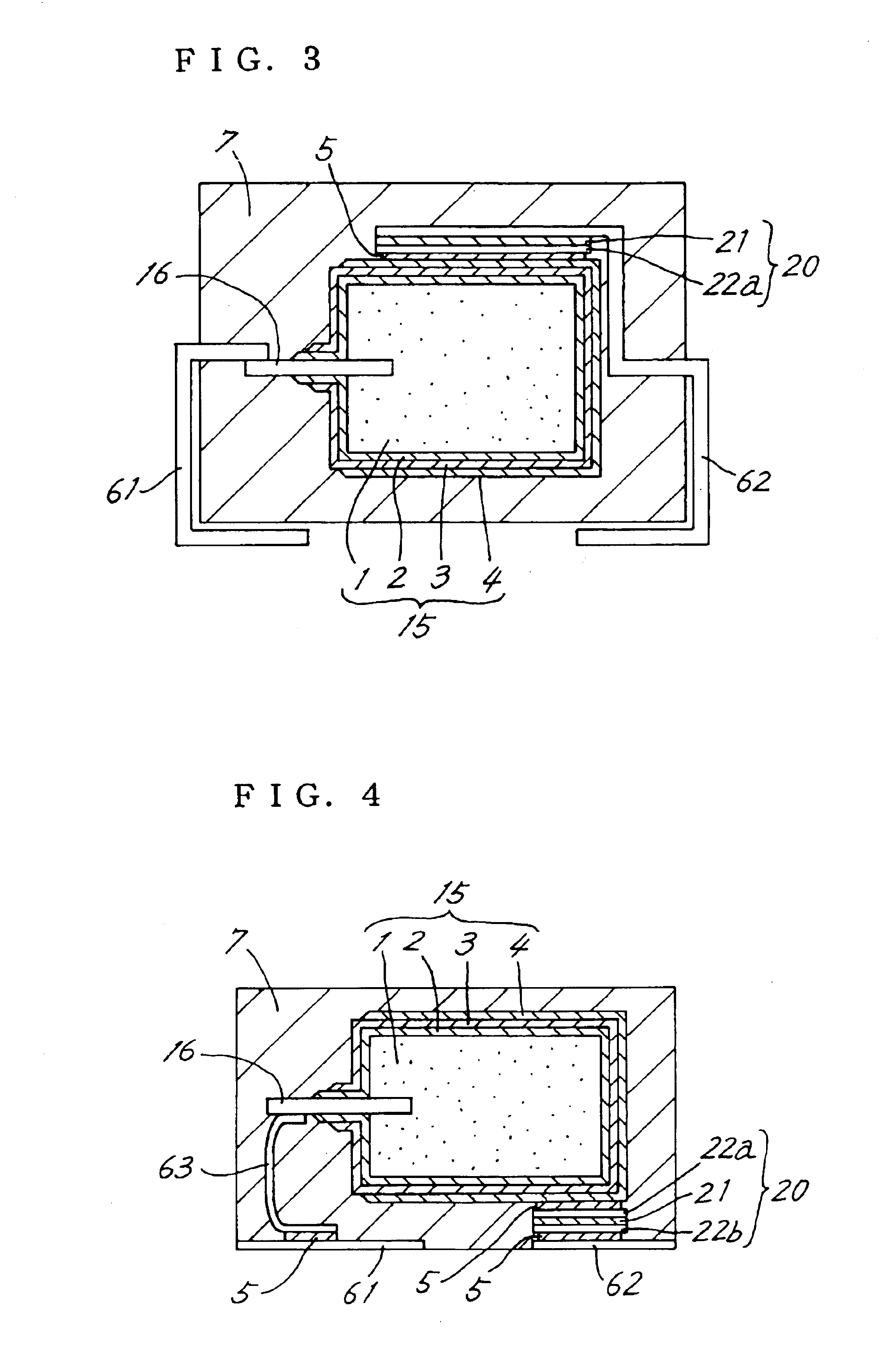
[0043]FIG. 3 is a view in vertical section and showing a solid electrolytic capacitor of second embodiment of the invention. The second electrode member 22b included in the first embodiment is omitted from the present embodiment, and the current control layer 21 is held between the first electrode member 22a and the cathode terminal member 62. The cathode terminal member 62 serves the function of the second electrode member 22b of the first embodiment. In other words, the cathode terminal member 62 partly serves as the second electrode member 22b shown in FIG. 1. Because of this construction, the solid electrolytic capacitor has a smaller number of components. If the first electrode member 22a, current control layer 21 and cathode terminal member 62 are prepared in the form of an element separate from the capacitor element 15, the process for fabricating the capacitor can be shortened.

[0044]Since it is desirable to sandwich the current control layer 21 between ele...

third embodiment

(Third Embodiment)

[0045]FIG. 4 is a view in vertical section and showing a solid electrolytic capacitor of third embodiment of the invention. According to this embodiment, the anode terminal member 61 and the cathode terminal member 62 are each in the form of a flat plate, and are positioned in a substantially same plane beneath the packaging resin portion 7 and spaced apart from each other. The current control means 20 is disposed under the anode body 1. The cathode terminal member 62 is disposed beneath the current control means 20. The first electrode member 22a of the current control means 20 is joined to the lower surface of the anode body 1 with the electrically conductive adhesive 5. The second electrode 22b is joined to the upper surface of the cathode terminal member 62 with the conductive adhesive 5.

[0046]The anode leading member 16 extends generally horizontally from the anode body 1, and the anode terminal member 61 is disposed under the anode leading member 16. The anod...


PUM

PropertyMeasurementUnit
melting pointaaaaaaaaaa
temperatureaaaaaaaaaa

Abstract

The invention provides a solid electrolytic capacitor which comprises a capacitor element including an anode body having an anode leading member, and a dielectric coating layer, a solid electrolyte layer and a cathode leading layer which are formed successively over a surface of the anode body. The anode leading member has an anode terminal member connected thereto, the cathode leading layer has a cathode terminal member connected thereto, and the capacitor element is covered with a packaging resin portion. The cathode terminal member is connected to the cathode leading layer with current control means provided therebetween. The current control means comprises a current control layer reversibly increasable in electrical resistance with overcurrent or excessive heat, and a pair of electrode members each in the form of a plate or foil and having the current control layer sandwiched therebetween. The electrode members are joined to the cathode leading layer and the cathode terminal member, respectively.

Description

FIELD OF THE INVENTION[0001]The present invention relates to solid electrolytic capacitors which are diminished in the self-generation of heat due to short-circuit malfunctions.BACKGROUND ART[0002]Typical solid electrolytic capacitors of the prior art have the construction shown in FIG. 14. A capacitor element 15 comprises a generally rectangular parallelepipedal anode body 1, and an anode leading member 16 in the form of a rod and embedded in the anode body 1. The anode body 1 is a sintered body of valve metal (such as tantalum, niobium, titanium, aluminum or the like). The anode body 1 has a dielectric coating layer 2 formed over the surface thereof by oxidizing. Formed over the dielectric coating layer 2 is a solid electrolyte layer 3, which in turn has a cathode leading layer 4 formed thereon. The solid electrolyte layer 3 is made from an electrically conductive inorganic material such as manganese dioxide, or an electrically conductive organic material such as a TCNQ complex sa...

Claims


Application Information

Patent Timeline
Patent Type & Authority Patents(United States)
IPC IPC(8): H01G2/00H01G9/00H01G9/04H01G9/008H01G9/012H01G2/14H02H7/16H02H7/00H01G9/15H01G9/12H01G9/042
CPCH01G9/0003H01G9/15H01G9/042Y10T29/417H01G9/12
Inventor KAMIGAWA, HIDENORIMORITA, KOUICHIIBUTA, HITOSHI
Owner TYCO ELECTRONICS RAYCHEM KK
Why Eureka
Try Eureka