Method for apparatus for polishing outer peripheral chamfered part of wafer

a technology of peripheral parts and apparatus, which is applied in the direction of grinding drives, manufacturing tools, lapping machines, etc., can solve the problems of defective subsequent process, poor production yield of subsequent process, and insufficient cleaning of chemicals used in etching process, so as to improve the productivity of the polishing process and reduce the polishing time

Inactive Publication Date: 2005-04-26
SHIN-ETSU HANDOTAI CO LTD
View PDF5 Cites 128 Cited by
  • Summary
  • Abstract
  • Description
  • Claims
  • Application Information

AI Technical Summary

Benefits of technology

[0014]The present invention has been made in view of the above-mentioned problems and has an object of reducing polishing time and improving productivity in a polishing process for the chamfered peripheral part of a wafer.
[0016]The present invention aims at rapidly extinguishing large surface roughnesses and deep scratches. Thus the chamfered peripheral part of a wafer is first polished by means of a rapid rate but giving a rough finish surface and then put a finish polishing on when the whole surface state becomes uniform so as to finish up to be a high grade surface of the chamfered peripheral part that has no process damages and small surface roughnesses. Hence the polishing time is extremely reduced and the productivity increases.
[0018]As described above, a particular part of a peripheral part of a wafer is susceptible to rough surface. Therefore a polishing can be performed by two separate steps of the first polishing process in which the particular part of a peripheral part of the wafer is polished and the second polishing process in which the whole part of a peripheral part of the wafer is polished for finishing. At this time, only {110} plane can be polished in case the particular part of the peripheral part of the wafer is {110} plane or the peripheral part can be polished on the condition that the part corresponding to the {110} plane is selectively polished. For example, the peripheral part is polished by changing a polishing pressure or a holding time of attaching to the polishing cloth and so on with regard to the part being {110} plane or not. Thus, when the part of {110} plane becomes indistinguishable from the other part, then the whole part of the peripheral part is successively polished for finishing, which leads to reduction of process time and improving productivity.
[0019]Further, the present invention is characterized by that polishing conditions are changed among a plurality of processes which consists of at least two polishing processes by changing a hardness of the polishing cloth and / or a particle size of the abrasives in the polishing slurry. These aforementioned conditions along with the polishing rate are important factors to determine the surface roughness and are also easily changeable.
[0021]Similarly, it is also a feature of the present invention to use in the second polishing process a polishing slurry having a smaller particle size of the abrasives in the polishing slurry than that in the first polishing process. Otherwise, a kind of abrasives in the polishing slurry can be varied such as in the first polishing process with a fumed silica having high polishing capability and then in the second polishing process With a colloidal silica of small particle size still more capable of improving surface roughness.
[0025]In accordance with the present invention, as an apparatus capable of performing rapidly and effectively the method of the present invention, in a polishing apparatus for polishing the chamfered periphery part of a wafer having a rotating drum affixed with a polishing cloth thereon, a wafer rotating part which press the chamfered peripheral part of the wafer against the rotating drum while rotates the wafer on it and a nozzle which supplies polishing slurry to the contact area of the polishing cloth to the chamfered peripheral part of the wafer, an apparatus is presented which is characterized by that the apparatus has a rotating drum affixed with a plurality of polishing clothes having different values of hardness thereon, a relative linear moving means which relatively moves a polishing spot on the clothes in the direction parallel to the affixed plane of the clothes wherein the moving range of the relative linear moving means is at least a wafer moving distance between the polishing spots of different clothes of a plurality of the polishing clothes.

Problems solved by technology

Consequently, if the wafer has a sharp peripheral edge of a right angle as it is cut, it is liable to give rise to mechanical defects such as chips and cracks which further cause particles attaching on the surface of the wafer to result in a bad production yield of the subsequent process.
If the peripheral part of the wafer has a coarse surface, chemicals used in an etching process are not perfectly cleaned so as to affect the subsequent process defectively.
Fragmental abrasive grains broken from the grindstone or the deformation of the grindstone in this process causes deep scratches on the surface.
On the other hand, the problems are roughness and damages induced by processing as far as the peripheral part of the wafer is concerned.
Therefore polishing time of the peripheral part becomes so long that a problem arises regarding a life of polishing cloth.
Consequently, these issues give rise to the necessity of the improvement in terms of productivity and cost in the process.
In a polishing process with a single condition, the peripheral part has often been polished excessively in order to equalize different surface spots of different surface roughness, which has led to reduction of productivity.

Method used


Image

  • Method for apparatus for polishing outer peripheral chamfered part of wafer
  • Method for apparatus for polishing outer peripheral chamfered part of wafer
  • Method for apparatus for polishing outer peripheral chamfered part of wafer

Examples


example 1

[0037]Using two sets of polishing apparatuses shown in FIG. 4, polishing for the chamfered peripheral part of a wafer was performed with a first polishing apparatus on the similar condition to that of Comparative Example 1 by rotating the wafer at 40 seconds per round as a rough polishing (a first polishing) and then with a second polishing apparatus on the similar condition to that of Comparative Example 2 as a fine polishing (a second polishing). The two separate sets of polishing apparatuses herein were constructed so as to be changed in sequence at the time of the first polishing and then the second polishing and so that the chamfered part of the wafer was contacted to each drum at the same set value of polishing pressure.

[0038]In the above described examples and comparative examples, the polishing was operated by rotating the wafer only one round at an operation and the surface roughness of the polishing part was measured. The shorter the time for one round, i.e. the more rapid...

example 2

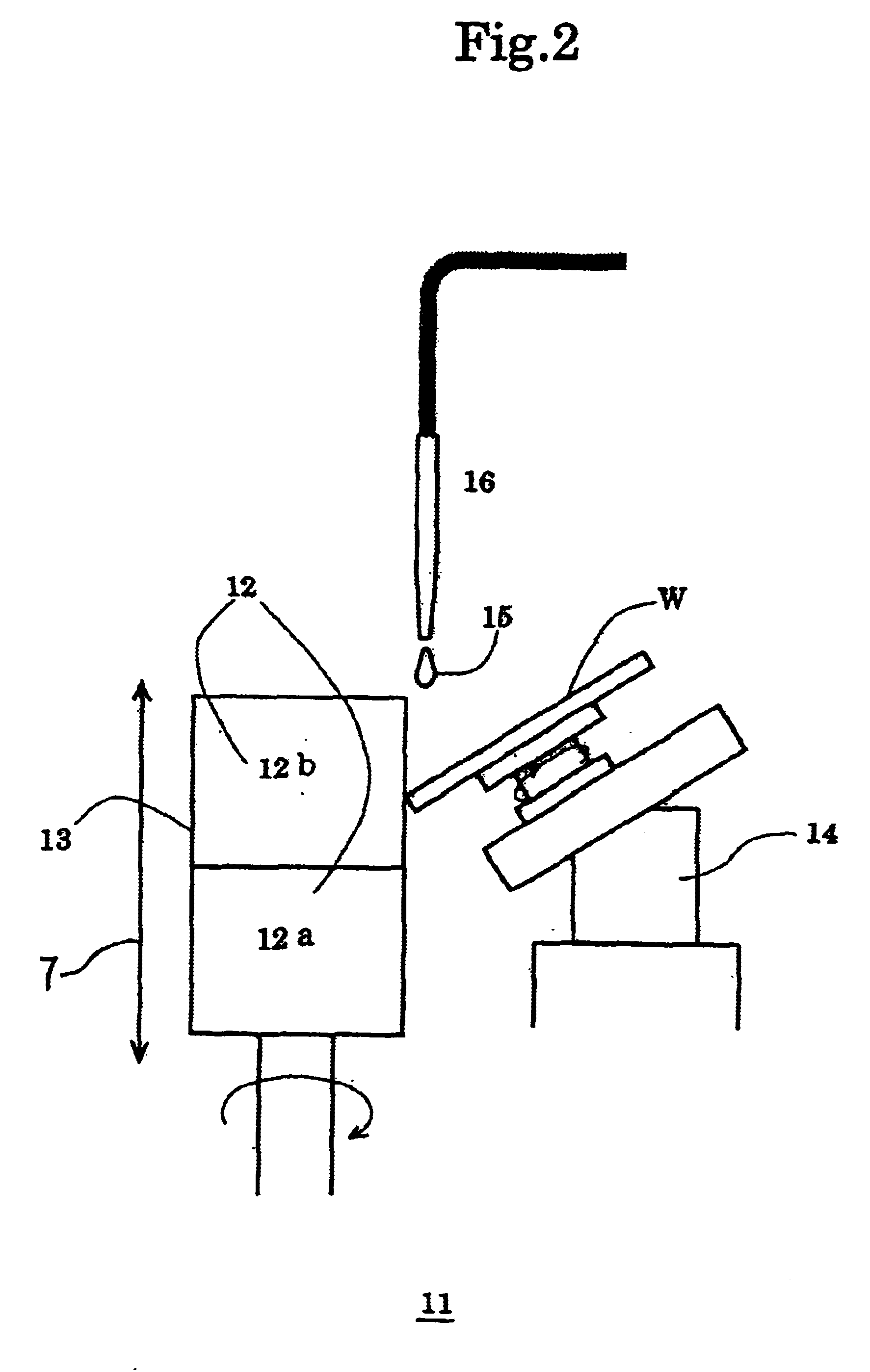
[0041]A second illustrative embodiment of the present invention will now be described with reference to FIG. 2.

[0042]A polishing apparatus 11 comprises a rotating drum 13 affixed with a polishing cloth 12 to the surface thereof, a wafer rotating part 14 which press the chamfered peripheral part of the wafer W against the rotating drum 13 while rotates the wafer thereon, a linear moving means which moves the rotating drum and the wafer rotating part relatively in up and down directions along the axis of the rotating drum 13 as illustrated by the arrow 7, and a nozzle 16 which supplies polishing slurry 15 to the contact spot of the polishing cloth to the chamfered peripheral part of the water W. The polishing apparatus 1 is also capable of controlling variably the wafer rotating rate and the processing pressure. Further, the polishing cloth 12a, 12b affixed to the rotating drum varied by two steps along the direction of the rotating axis of the rotating drum so as to vary the hardness...

example 3

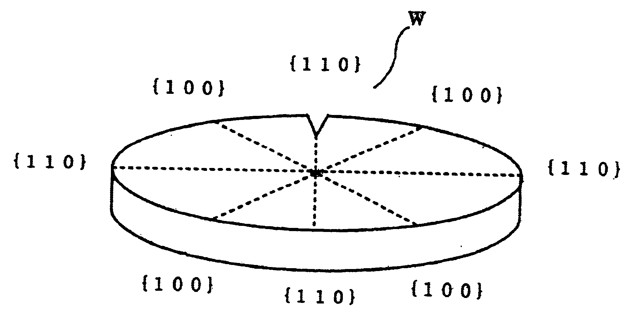
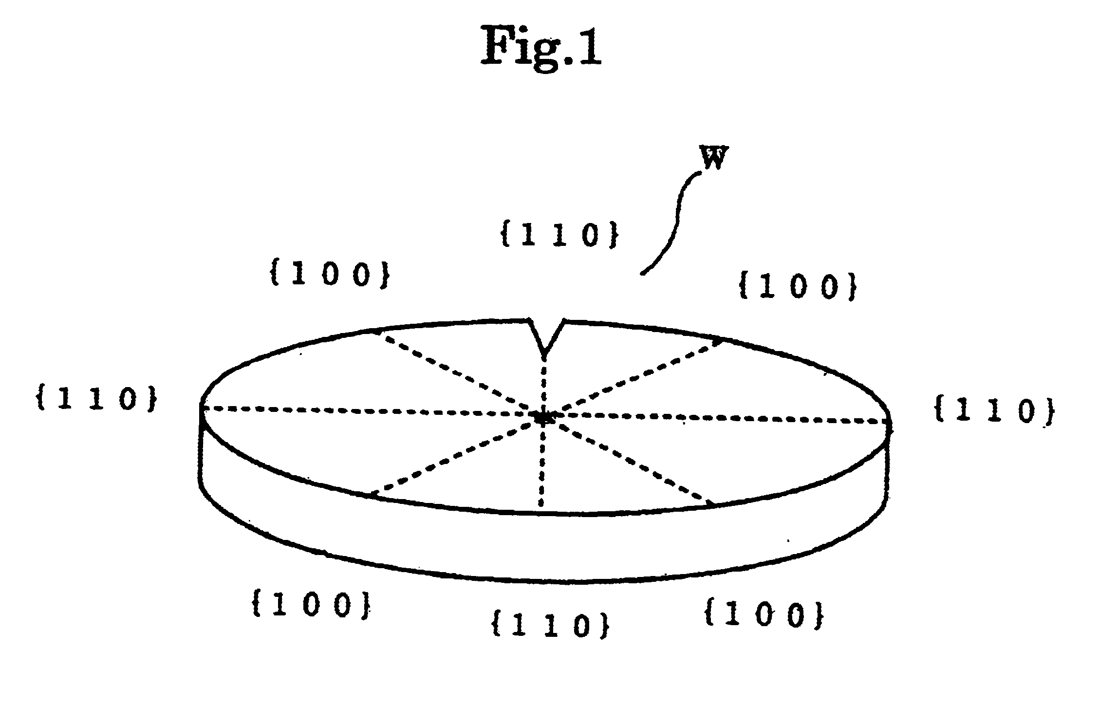
[0046]The region around {110} plane of the chamfered peripheral part of a wafer was polished as a first polishing and then the whole chamfered peripheral part was polished on the other condition as a second polishing. The first polishing was performed using two apparatus shown in FIG. 4 having a cloth of unwoven type polishing cloth of Asker c hardness of 62 with slurry containing fumed silica. The region around {110} plane of the chamfered peripheral part of a wafer was polished at a low rate of wafer rotation and with a high pressing pressure to the cloth. The more specifically, the region around {110} plane, i.e. the ±15° angle region from the center spot of direction, of the chamfered peripheral part of a wafer was polished at a 2 / 3 rate of wafer rotation compared to the other part with a pressing pressure of 1.5 times as strong as the other part so as to improve the roughness of the {110} plane region particularly.

[0047]Thus the roughness of the {110} plane was improved up to ...


PUM

PropertyMeasurementUnit
diameteraaaaaaaaaa
optical roughness gaugeaaaaaaaaaa

Abstract

In a process for polishing the chamfered peripheral part of a wafer using a polishing cloth while supplying a polishing slurry in order to improve productivity of the process by reducing a polishing time, at least two steps of polishing processes are performed in sequence. The process comprises a first polishing process to polish a particular part, e.g. the part corresponding to the {110} plane of a peripheral part of the wafer and a second polishing process in which the whole part of a peripheral part of the wafer is polished for finishing by means of varying a hardness of the polishing clothes and / or a particle size of abrasives in the slurry such as the hardness of the polishing cloth in the second polishing process being softer than that of in the first polishing process and a particle size of abrasives in the slurry in the second polishing process being finer than that of in the first polishing process.

Description

BACKGROUND OF THE INVENTION[0001]1. Fields of the Invention[0002]The present invention relates to a method for mirror polishing the chamfered peripheral part of a wafer and an apparatus for the same.[0003]2. Description of the Related Art[0004]The manufacturing process for mirror wafers of such as silicon semiconductor or compound semiconductor, is outlined as follows. A single crystal ingot first manufactured by pulling method or the like, is sliced into disc shape to obtain as-sliced wafers Subsequently, a lapping process is conducted in order to produce a flatness of the surface and a parallelism between the front and back surfaces of the as-sliced waters by grinding extremely uneven layers produced in the slicing process As the wafer having gone through these mechanical processes have a damage layer, that is, a deteriorated layer by mechanical impact on its surface, that layer is removed by chemical etching. To finish the wafer process, the wafer is polished to a mirror surface....

Claims


Application Information

Patent Timeline
Patent Type & Authority Patents(United States)
IPC IPC(8): B24D5/14B24D9/00B24D5/00B24D9/04B24B51/00B24B9/06H01L21/304H01L21/02B24B37/00B24B37/20B24B37/24
CPCB24B9/065B24B51/00H01L21/02021B24D9/04B24D5/14H01L21/304
Inventor MIZUSHIMA, KAZUTOSHIMIURA, NAKAJISEKINE, YASUHIROSUZUKI, MAKOTOTOMII, KAZUYA
Owner SHIN-ETSU HANDOTAI CO LTD
Why Eureka
Try Eureka