Hydrophobic membrane materials for filter venting applications

Inactive Publication Date: 2005-04-26
PALL CORP
View PDF44 Cites 117 Cited by
  • Summary
  • Abstract
  • Description
  • Claims
  • Application Information

AI Technical Summary

Problems solved by technology

Treating PTFE membranes with steam can cause pore blockage due to condensation of oil from the machinery used to generate the steam.
The resulting loss of air permeability reduces the membrane's ability to serve as an air vent.
Although chemical sterilization minimizes exposure of the membrane to oil, chemical sterilization uses toxic chemicals and can generate byproducts, which cause waste disposal problems.
PTFE may become unstable when exposed to ionizing radiation.
Irradiated PTFE membranes have greatly reduced mechanical strength and cannot be used in applications where they are subjected to even moderate pressures.
Perhaps the two biggest drawbacks to PTFE as a filter for v

Method used


Image

  • Hydrophobic membrane materials for filter venting applications
  • Hydrophobic membrane materials for filter venting applications
  • Hydrophobic membrane materials for filter venting applications

Examples


example 1

[0082]A casting solution was prepared containing 15 wt. % Dyneon™ THV 220A, 5 wt. % n-butanol (Crown Chemical of San Diego, Calif.) and 80 wt. % DMF (E. I. du Pont de Nemours and Company of Wilmington, Del.) as the solvents. The Dyneon™ THV 220A was added to the solvents and the mixture was heated to about 50 to 60° C. with mixing. A membrane was cast onto a moving belt of polyethylene coated paper using a casting knife with a knife gap of approximately 0.20 mm (approximately 8 mils). The solution was cast at room temperature. The membrane was exposed to air (at room temperature, 60% R.H.) for approximately 1 to 2 seconds before quenching. The membrane was quenched in a water bath having a temperature of about 20° C. for more than 10 minutes.

[0083]After quenching, the membrane was rinsed with deionized water and then air-dried at room temperature for approximately 30 minutes. The membrane was hydrophobic (not wettable by water). The membrane was tested for water penetration pressure...

example 2

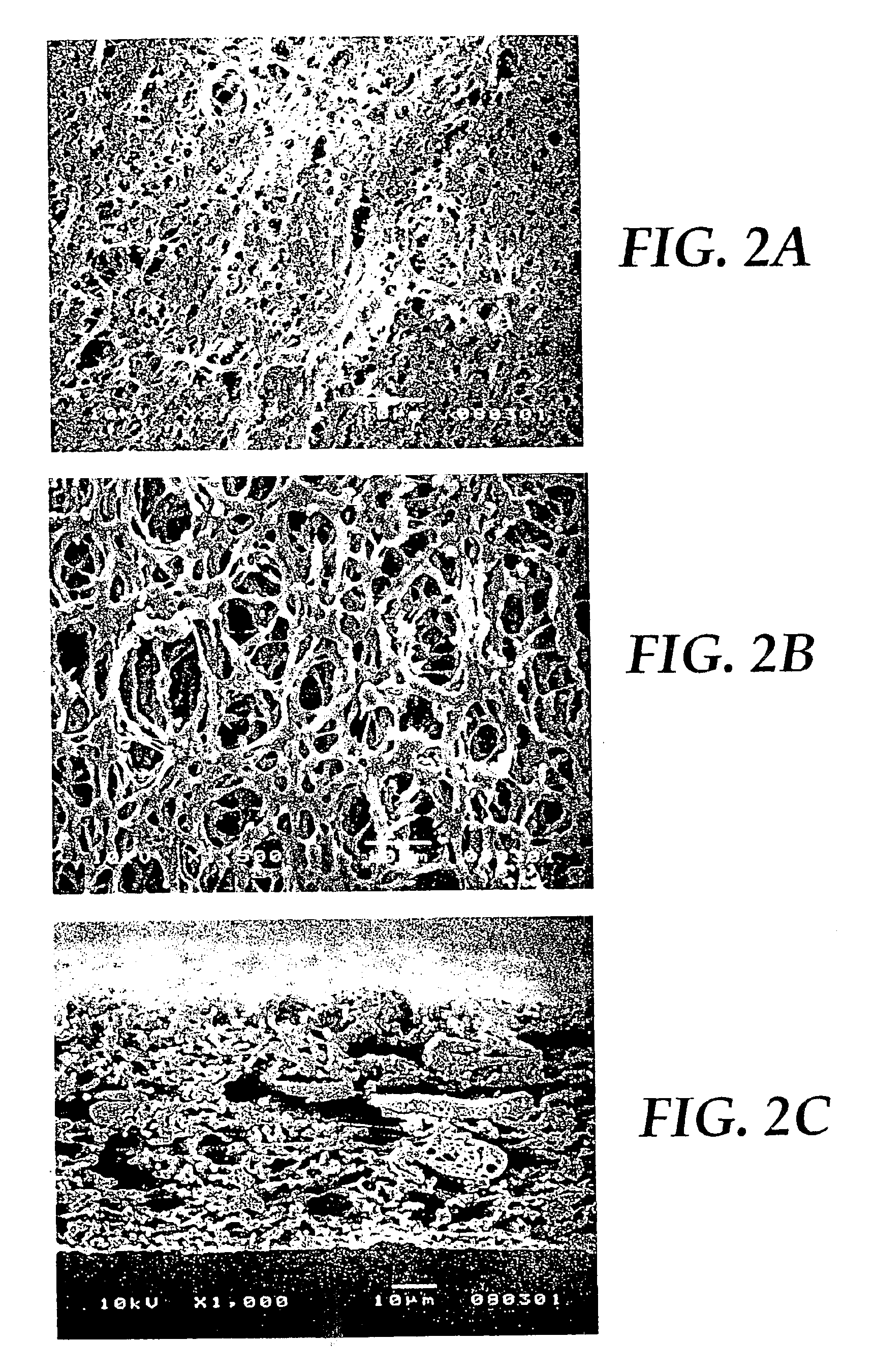
[0084]A casting solution was prepared containing 15 wt. % Dyneon™ THV220A and 85 wt. % DMF as the solvent using the method as described in Example 1. The resulting membrane was hydrophobic (not wettable by water). The membrane was tested for water penetration pressure and water flow as described in Example 1. The membrane exhibited a 7000 ml / min water flow rate and a water penetration of 6 psi. FIG. 2a provides a SEM image of the skin side of the membrane, FIG. 2b provides a SEM image of the dull side of the membrane, and FIG. 2c provides a SEM image of the cross-section of the membrane. The membrane was asymmetric (degree of asymmetry of approximately 50:1) and had a mean flow pore size of 3.3 μm.

example 3

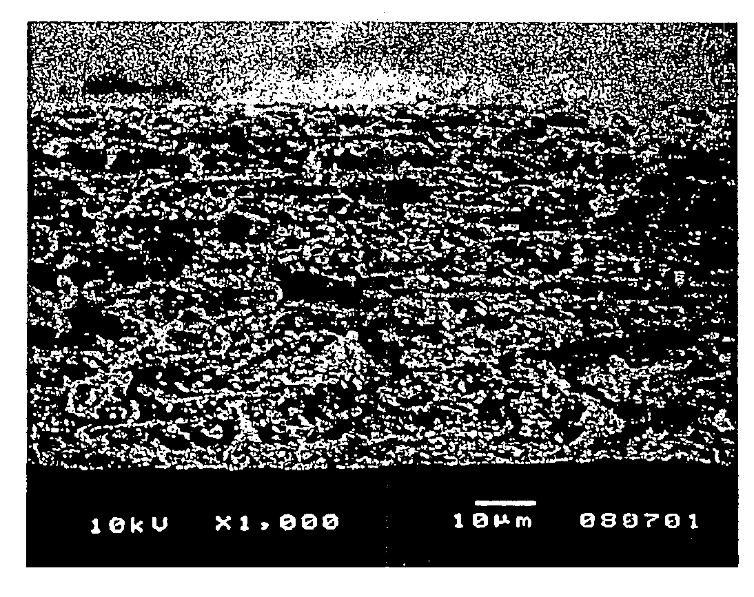
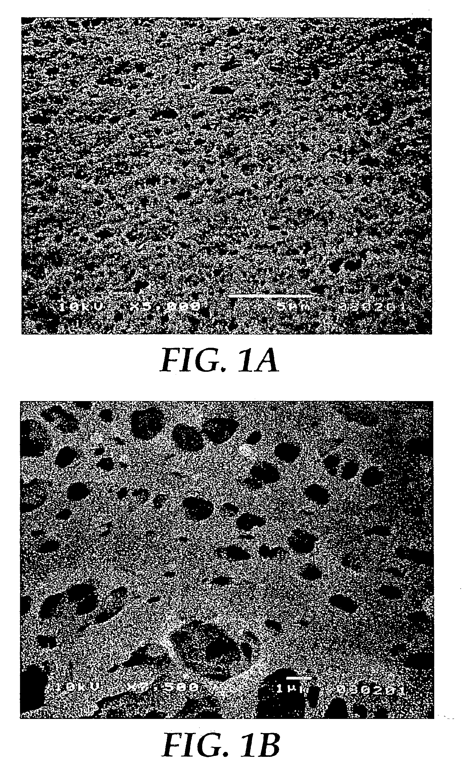
[0085]A casting solution was prepared containing 15 wt. % Dyneon™ THV220A, 10% n-butanol, and 75 wt. % DMF as the solvent using the method as described in Example 1. The resulting membrane was hydrophobic (not wettable by water). The membrane was tested for water penetration pressure as described in Example 1. The membrane exhibited a water penetration of 50 psi. FIG. 3a provides a SEM image of the skin side of the membrane, FIG. 3b provides a SEM image of the dull side of the membrane, and FIG. 3c provides a SEM image of the cross-section of the membrane. The membrane was asymmetric (degree of asymmetry of approximately 5:1) and had a mean flow pore size of 0.18 μm.


PUM

PropertyMeasurementUnit
Temperatureaaaaaaaaaa
Dispersion potentialaaaaaaaaaa
Hydrophobicityaaaaaaaaaa

Abstract

The present invention relates to filtration media having both hydrophobic (water-repellent) properties. The filtration media are produced using a fluorothermoplastic material, such as a terpolymer of tetrafluoroethylene, vinylidene fluoride, and hexafluoropropylene. The invention also relates to methods of preparing such filtration media using casting solution phase inversion.

Description

RELATED APPLICATION[0001]This application is a division of application Ser. No. 10 / 123,074, filed Apr. 12, 2002, now U.S. Pat. No. 6,811,696.FIELD OF THE INVENTION[0002]The present invention relates to filtration media having both hydrophobic (water-repellent) properties. The filtration media are produced using a fluorothermoplastic material, such as a terpolymer of tetrafluoroethylene, vinylidene fluoride, and hexafluoropropylene. The invention also relates to methods of preparing such filtration media using casting solution phase inversion.BACKGROUND OF THE INVENTION[0003]Hydrophobic filters are used in filtration of gases, in venting filters, and as gas vents. These hydrophobic filters allow gases and vapors to pass through the filter while liquid water is repelled by the filter.[0004]Polytetrafluoroethylene (PTFE) has been the most commonly used material in filters for gas venting. PTFE is chemically and biologically inert, has high stability, and is hydrophobic. PTFE filters th...

Claims


Application Information

Patent Timeline
IPC IPC(8): B01D67/00B01D71/32B01D71/00B01D71/36B01D19/00B01D69/06B01D69/10
CPCB01D19/0031B01D67/0011B01D67/0013B01D69/02B01D71/36B01D71/32B01D2325/022B01D2323/12B01D2323/38
Inventor WANG, I-FANMCDONOGH, RICHARDRUDOLPH, JR., JAMES E.
Owner PALL CORP
Why Eureka
Try Eureka