RF power supply with integrated matching network

a technology of matching network and power supply, which is applied in the direction of multiple-port network, plasma technique, coating, etc., can solve the problems of mismatching impedance between the standard fifty-ohm output impedance of the rf generator and the input, high cost of these prior-art rf power supplies, and large fraction of the total system cost, etc., to achieve fast control, optimize efficiency, and eliminate the use of mechanical components

Inactive Publication Date: 2005-05-03
MKS INSTR INC
View PDF23 Cites 204 Cited by
  • Summary
  • Abstract
  • Description
  • Claims
  • Application Information

AI Technical Summary

Benefits of technology

[0016]In a closely-coupled system, there is no need to employ a discrete, separate cable to connect an RF generator to a network or to the load of a plasma processing tool. Hence, potential instabilities due to cable selection are eliminated. Further embodiments eliminate use of mechanical components within an impedance matching network. This removes instability due to such components as motor-driven vacuum capacitors in the matching network.
[0036]In a fifth aspect, the invention features a method for stabilizing a plasma. The method includes generating electromagnetic radiation with an RF generator that includes an H-bridge, the electromagnetic radiation having a power that is related to a DC voltage applied to an RF generator bus. The method further includes electromagnetically coupling the electromagnetic radiation to an impedance matching network, sensing a power of the electromagnetic radiation propagating through the matching impedance, coupling the electromagnetic radiation to a plasma and adjusting the DC voltage applied to the RF generator bus in response to the sensed power of the electromagnetic radiation propagating through the matching impedance so as to maintain a substantially constant power in the plasma.

Problems solved by technology

Prior art RF power supplies used in plasma sources for plasma processing equipment generally have expensive and complex power generation and delivery systems.
In addition, precision instrumentation is usually required to control the actual power reaching the plasma The cost of these prior art RF power supplies can be a considerable fraction of the total system cost.
A matching network is required because the load represented by the process chamber and the plasma can vary widely and rapidly, causing mismatches in impedance between the standard fifty-ohm output impedance of the RF generator and the input of the load.
A mismatch in the impedance of the generator and the plasma source causes great stress on electronics devices in the RF generator and the matching network and can cause premature failure because of either electrical or thermal stress or both.
Consequently, the reliability of prior art RF generators and matching networks is relatively low and is considered to be below desired standards of the semiconductor industry.
The relatively low reliability increases the total cost of ownership (COO) of the plasma processing tool, since time must be spent in diagnosing failures and repairing or replacing defective RF equipment.
Impedance mismatch also causes the power delivered to the plasma to vary, which can cause process inconsistency both within a chamber for successive substrates and among similar chambers.
The dynamic tuning range, however, is relatively low.
Such a wide frequency range is unacceptable for processing reasons and also because of potential interference with other equipment protected using narrow-band filters.
Mechanical motors, however, are relatively slow, while vacuum variable capacitors are expensive.
The matching network is complex because it requires many switches.
PIN diodes are susceptible to breakdown and are relatively expensive.
This can cause discontinous jumps in the resonant frequency and impedance seen by the RF supply, as well as off-resonance operation of the RF supply while the resonant frequency is re-established by a feedback control loop.
Off-resonance operation can cause significant stress on field effect transistor (“FET”) switches.

Method used


Image

  • RF power supply with integrated matching network
  • RF power supply with integrated matching network
  • RF power supply with integrated matching network

Examples


Embodiment Construction

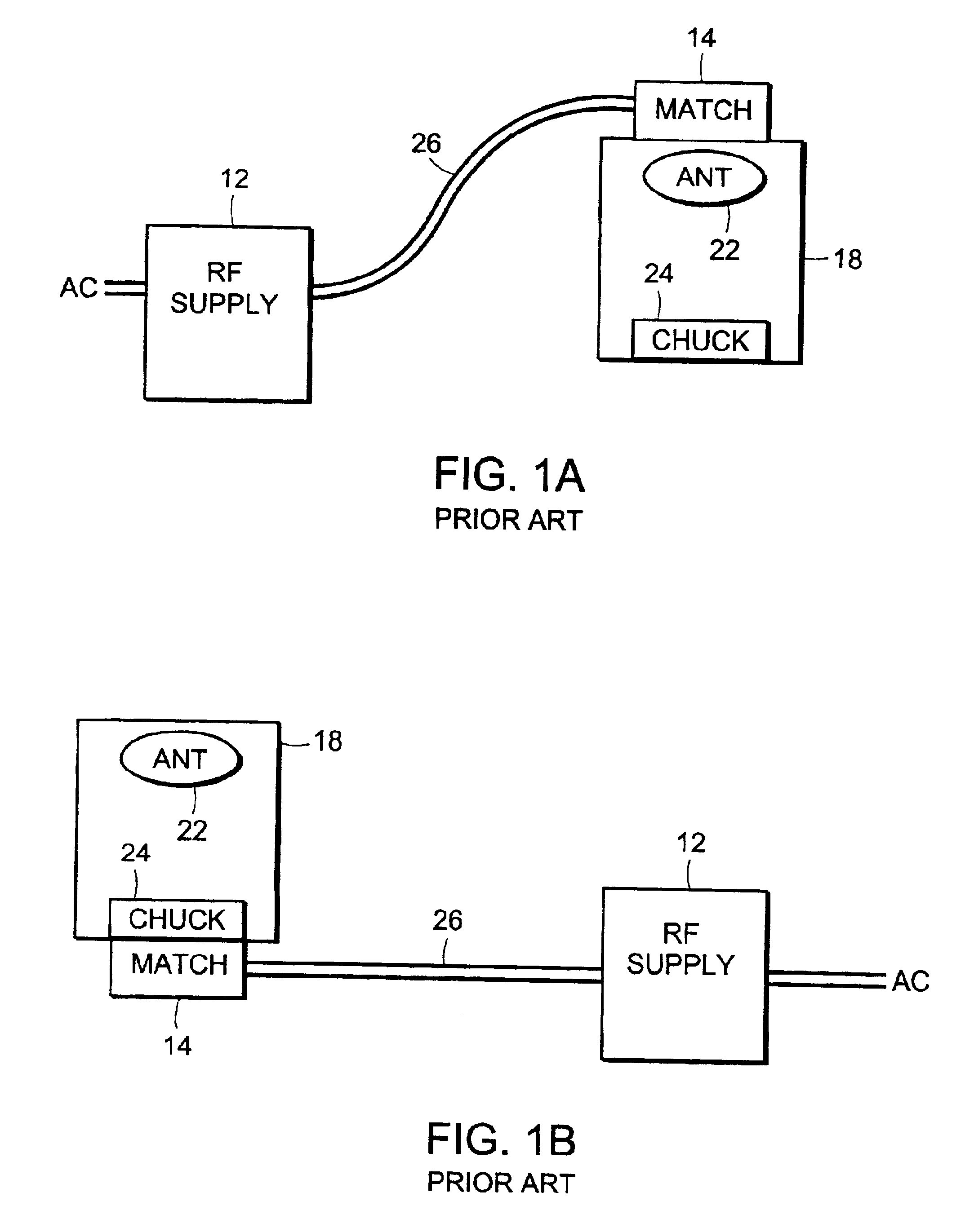
[0072]FIGS. 1a and 1b illustrate prior art plasma processing systems that includes a separate RF generator 12 and matching network 14. A plasma processing system includes an antenna 22, a chuck 24 for holding substrates to be processed and a process chamber 18. The matching network 14 is positioned proximate to the antenna 22 or the chuck 14, depending on the processing system configuration.

[0073]The RF generator 12 is positioned a significant distance away from the process chamber 18, where a plasma is created. RF cables 26 connect the output of the RF generator 12 to the input of the matching network 14. Other prior art plasma processing systems enclose the matching network 14 and RF generator 12 in the same enclosure in order to save space. The combined unit may be located either remote from the process chamber 18 or proximate to process chamber 18. The output of the matching network 14 is attached to an antenna 22 that is designed to create a plasma in the plasma source 16. Some...


PUM

PropertyMeasurementUnit
frequencyaaaaaaaaaa
frequencyaaaaaaaaaa
impedanceaaaaaaaaaa

Abstract

The invention features an RF plasma generator. The RF plasma generator includes a variable frequency RF generator, comprising an H-bridge and an RF output. The RF generator generates electromagnetic radiation having a power. The RF plasma generator further includes a matching network that includes at least one variable impedance component. The matching network also includes a first port that is electromagnetically coupled to the output of the RF generator and a second port. The RF plasma generator also includes a load that is electromagnetically coupled to the second port of the matching network, and a plasma chamber for containing a plasma having a power. The plasma chamber is electromagnetically coupled to the load and receives electromagnetic radiation having a power from the load. Adjusting at least one of the frequency of the RF generator and the variable impedance component in the matching network changes the power in the plasma.

Description

RELATED APPLICATIONS[0001]This application claims the benefit of U.S. Provisional Patent Application Ser. No. 60 / 234,022, filed Sep. 20, 2000, the entire contents of which are hereby incorporated by reference.FIELD OF THE INVENTION[0002]The present invention relates generally to RF and microwave power supplies and to RF and microwave plasma processing equipment. In particular, the present invention relates to RF and microwave power supplies for generating RF or microwave plasmas in a plasma processing chambers.BACKGROUND OF THE INVENTION[0003]Radio Frequency (RF) or microwave power supplies (hereafter “RF power supplies”) are widely used in semiconductor and industrial plasma processing equipment to generate plasmas in a process chamber. Plasma processing is used for a wide variety of applications, including etching of materials from substrates, deposition of materials on to substrates, cleaning of substrate surfaces, and modification of substrate surfaces. The frequency and power l...

Claims


Application Information

Patent Timeline
Patent Type & Authority Patents(United States)
IPC IPC(8): C23C16/00H05H1/00
CPCH01J37/32082H01J37/32174H01J37/32183H03H7/40H03F1/565H03F2200/378H03F2200/387H03F2200/391
Inventor GOODMAN, DANIELBORTKIEWICZ, ANDRZEJALLEY, GARY D.HORNE, STEPHEN F.HOLBER, WILLIAM M.
Owner MKS INSTR INC
Why Eureka
Try Eureka