
Power chip set for a switching mode power supply having a device for providing a drive signal to a control unit upon startup

a power chip and switching mode technology, applied in the field of switching mode power supply integrated circuits, can solve the problems of complicated circuits and expensive manufacturing processes, and achieve the effect of avoiding expensive ic manufacturing processes and small chip area

Inactive Publication Date: 2005-05-03
ANPEC ELECTRONICS CORPORATION
View PDF7 Cites 14 Cited by
  • Summary
  • Abstract
  • Description
  • Claims
  • Application Information

AI Technical Summary

Benefits of technology

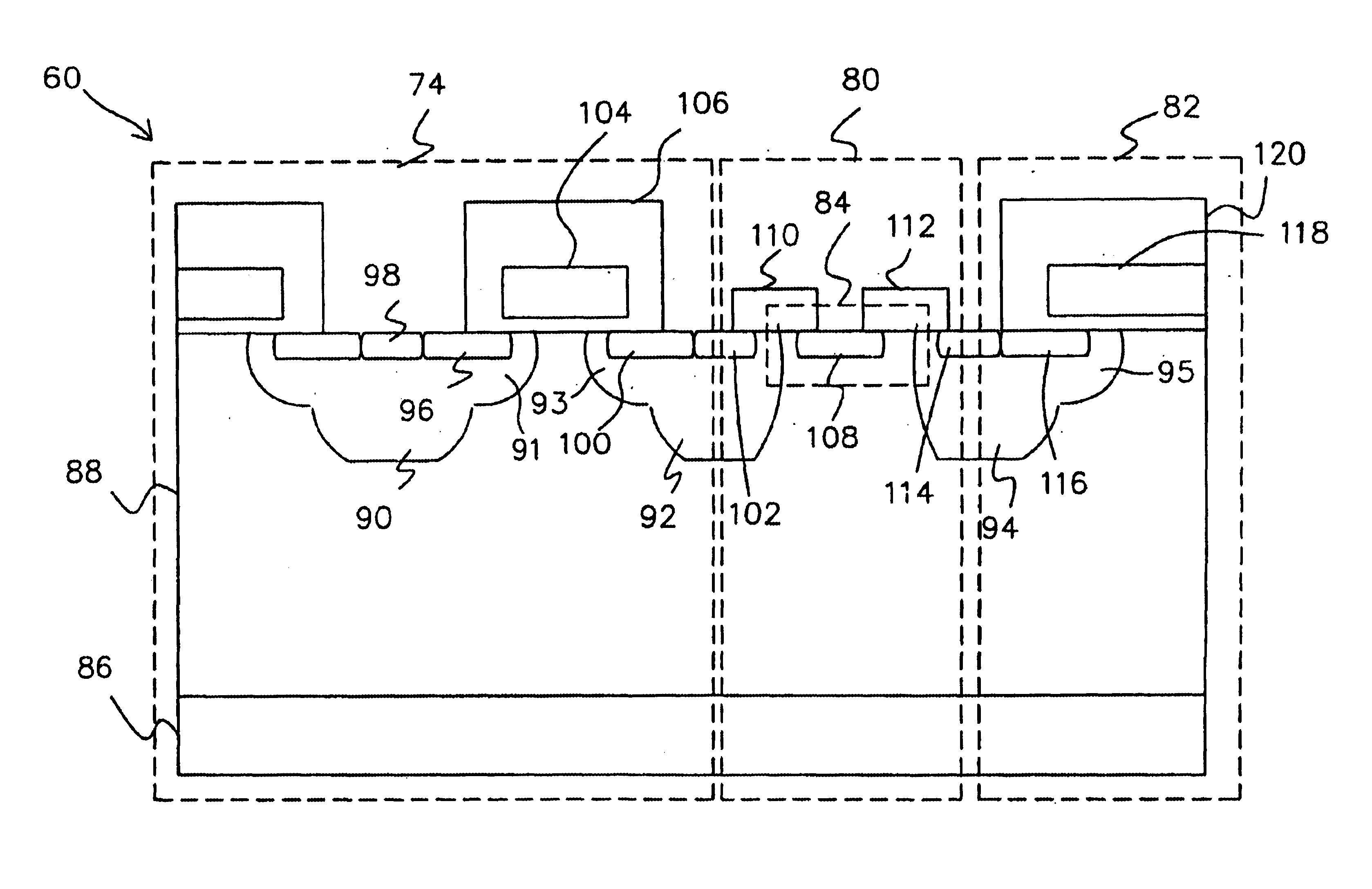
[0010]One advantage of the present invention resides in that the JFET is manufactured in a process compatible with the power MOS, and therefore the JFET and the high voltage switching power MOS transistor are integrated on a single chip.
[0011]Another advantage of the present invention resides in that the chip set is constituted of the high voltage chip and the control unit chip, such that expensive IC manufacturing process is avoided and a smaller chip area is obtained. The chip set can be packaged into a module.

Problems solved by technology

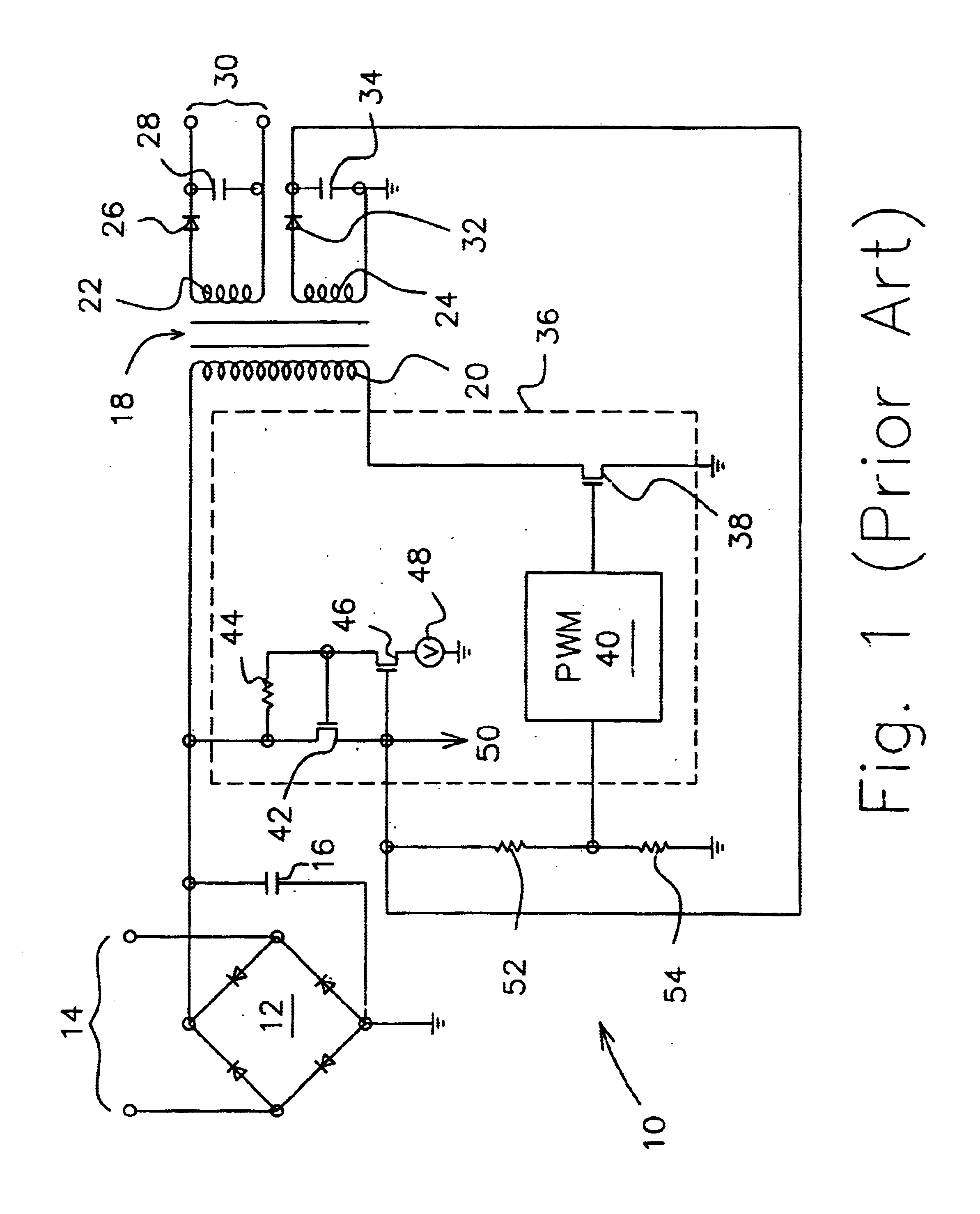
However, complicated circuits and expensive manufacturing processes are presented in these prior arts.

Method used


Image

  • Power chip set for a switching mode power supply having a device for providing a drive signal to a control unit upon startup
  • Power chip set for a switching mode power supply having a device for providing a drive signal to a control unit upon startup
  • Power chip set for a switching mode power supply having a device for providing a drive signal to a control unit upon startup

Examples


Embodiment Construction

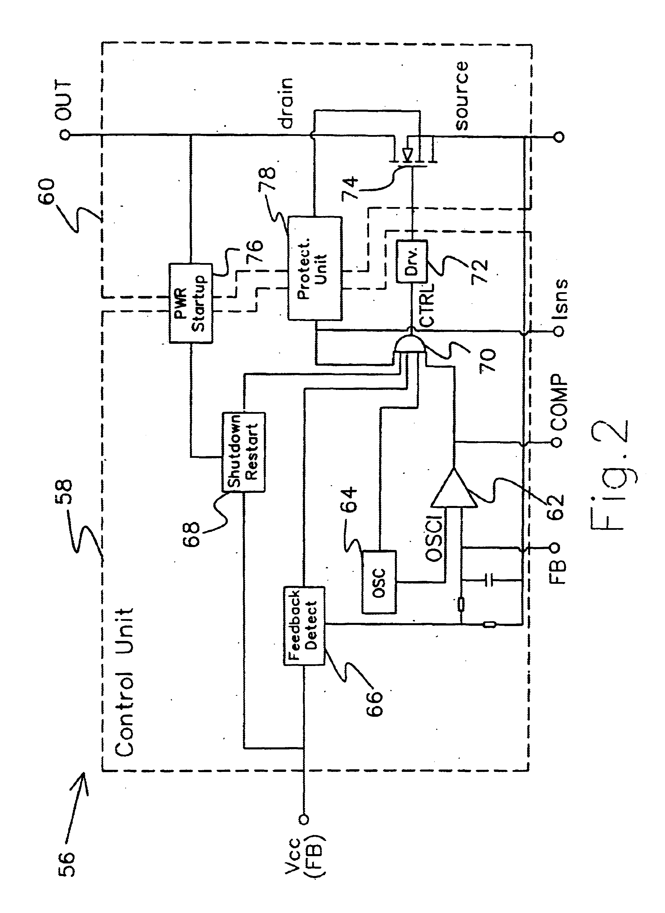
[0017]One embodiment according to the present invention is shown in FIG. 2, in which a power module 56 for a SMPS comprises a chip set composed of a control unit chip 58 and a high voltage chip 60. The high voltage chip 60 contains high voltage circuit elements, while all control circuits contained in the control unit chip 58 being not applied with high voltage.

[0018]Provided in the control unit circuit 58, a pulse width modulation comparator 62 receives and compares two signals, i.e., a feedback signal FB and an oscillation signal OSCl form an oscillator 64, through its two input terminals respectively. As a result, an output oscillation signal COMP with a selected oscillation frequency and duty cycle is generated by the pulse width modulation comparator 62. The feedback signal FB is also connected to an over voltage and under voltage detection and feedback detection unit 66 whose output signal together with an output signal of a shutdown / auto restart unit 68, an output signal of t...


PUM


Abstract

A power chip set for a switching mode power supply includes a high voltage chip and a control unit chip. The high voltage chip contains a switching power metal-oxide-semiconductor (MOS) transistor being turned on / off under control of an output signal from the control unit, and a junction field effect transistor (JFET) coupled between a drain of the switching power MOS transistor and a power terminal of the control unit to serve as a start up element for driving the control unit during initiation, in which the JFET has a negative threshold voltage and the absolute value thereof is equal to the voltage for driving the control unit. The JFET structure in the high voltage chip further includes a Zener diode for over voltage protection of the control unit. The high voltage chip further contains a current-sense power MOS transistor coupled with the drain of the switching power MOS transistor for detecting a drain current of the switching power MOS transistor. The chip set can be packaged into a power module.

Description

CROSS-REFERENCE TO RELATED APPLICATION[0001]The present application is a continuation of U.S. patent application Ser. No. 09 / 882,848, filed Jun. 15, 2001, abandoned which is a continuation of U.S. patent application Ser. No. 09 / 563,586, filed May 3, 2000 (now U.S. Pat. No. 6,259,618, issued on Jul. 10, 2001).FIELD OF THE INVENTION[0002]The present invention relates to an integrated circuit (IC) of a switching mode power supply (SMPS), and more particularly to a power chip set for an SMPS.BACKGROUND OF THE INVENTION[0003]It is a principal concern of the cost to manufacture a power supply in selecting between power supply types to be used in particular application and the components selected to construct them. Since integrated circuit technology has advanced such that a majority of the complex switching mode circuits can be integrated on a single chip, switching mode power supplies have become cost competitive with much simpler linear power supplies.[0004]A prior art flyback power sup...

Claims


Application Information

Patent Timeline
Patent Type & Authority Patents(United States)
IPC IPC(8): H01L29/66H01L29/78H02M1/00H02M3/335H03K17/082H03K17/04H03K17/042H02M3/24H02M1/36
CPCH01L29/7802H02M1/36H03K17/0822H03K17/04206H02M3/33507H01L27/085H01L29/7808H01L29/7815
Inventor LIAW, CHORNG-WEITIEN, HAU-LUENLIN, WEI-JYELIN, MING-JANGSHIUE, TIAN-FURECHENG, HUANG-CHUNGHSU, CHING-HSIANG
Owner ANPEC ELECTRONICS CORPORATION
Learn More