Field emission device using a reducing gas and method for making same

a field emission device and reducing gas technology, applied in the direction of discharge tube luminescnet screen, gas filling substance selection, dynamo-electric machines, etc., can solve the problems of high oxidation rate, and short operation life time, and achieve the effects of short operation life, short operation life, and severe constraints in regards to the choice of luminophors

Inactive Publication Date: 2005-05-03
COMMISSARIAT A LENERGIE ATOMIQUE ET AUX ENERGIES ALTERNATIVES
View PDF13 Cites 7 Cited by
  • Summary
  • Abstract
  • Description
  • Claims
  • Application Information

AI Technical Summary

Benefits of technology

[0004]Microdot screens are flat cathode ray tubes that operate under vacuum. These screens comprise a cathode (notably made out of cathodic conductors, grids and microdots) and an anode (made out of conductors and luminophors). In order to maintain the vacuum, an element known as a getter is used, as is the case with conventional cathode ray tubes. A getter is an element that, once it has been activated by heating under vacuum, can fix the gases desorbed by the device and maintain the vacuum level required for the device to work properly.
[0012]According to a third approach, a material sensitive to oxidation (such as molybdenum) could be used in the presence of oxidisable luminophors, but by creating, within the interior volume of the screen, a reducing atmosphere that can prevent this oxidation occurring and which can thus maintain the emissive material in its most favourable state. This third approach is particularly interesting, because it allows molybdenum to be used as the emissive material, while at the same time allows a wide choice as regards the type of luminophor.
[0019]A hydrogen atmosphere effectively makes it possible to stabilise the current in trichromic screens for several thousand hours. However, this hydrogen based process has the following disadvantages.
[0023]According to the present invention, it is proposed that the disadvantages of the prior art may be overcome by using a NxHy type gas, preferably ammonia NH3, as a reducing gas instead of hydrogen. A partial pressure of NH3 makes it possible to avoid the oxidation of the dots and thus to ensure that the cathodes have a long operational life.
[0024]This gas NxHy is not evacuated, or is only evacuated to a very small extent, by the getters and is therefore compatible with getters known to those skilled in the art, which have very good evacuating characteristics. It has, in addition, the advantages of having very low toxicity, is non-explosive and presents no safety problems. It is therefore easy to use industrially.

Problems solved by technology

In the case of colour screens, which use three different luminophors to obtain emissions in the red, green and blue, the oxidation is generally high and leads to short operational life times, of less than 100 hours.
However, in the case of colour screens, this imposes very severe constraints as regards the choice of luminophors and is today very costly.
However, this hydrogen based process has the following disadvantages.
The quantity of getter that needs to be introduced is high (around 0.5 g for a 5 inch screen), which can lead to cost and cluttering problems, especially when large screens are involved.
Torr per gram of getter), which, given the volume of the screen, can lead to the manufacturer having to assemble the screen under a hydrogen pressure close to atmospheric pressure.
These conditions are difficult to implement in industrial conditions and, in particular, pose difficult safety problems, which can only be overcome by resorting to costly solutions.

Method used


Image

  • Field emission device using a reducing gas and method for making same
  • Field emission device using a reducing gas and method for making same
  • Field emission device using a reducing gas and method for making same

Examples


example 1

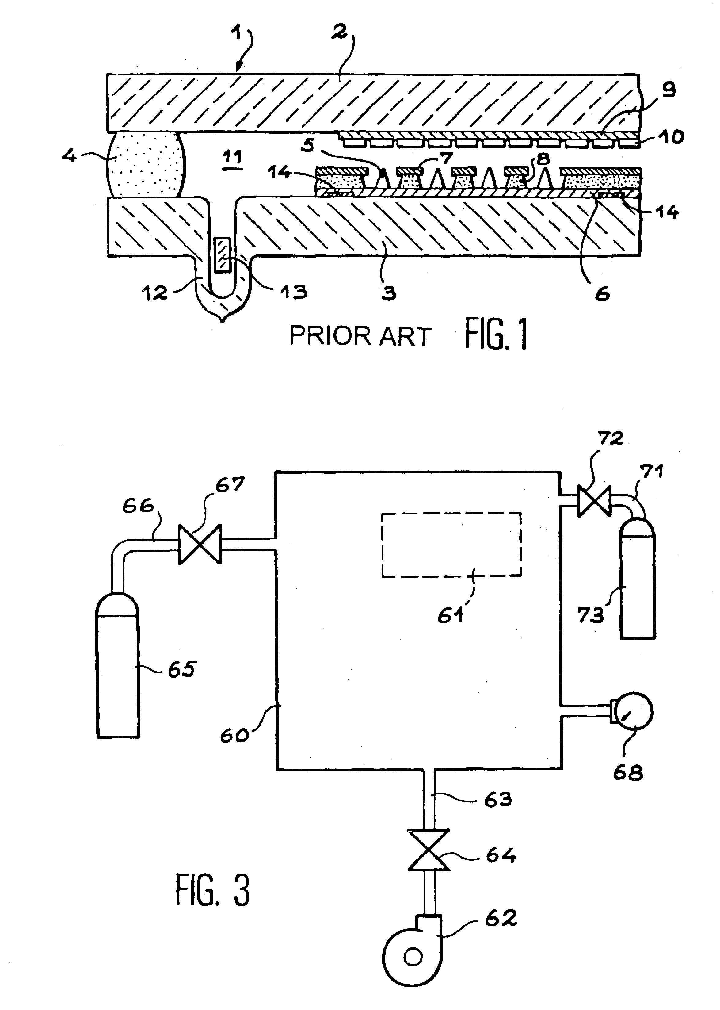
[0086]A microdot screen 20, of the type shown in FIG. 1, for example 6 inches (15.25 cm) diagonal width, is assembled under vacuum or under a controlled atmosphere by heating to a temperature between 450° C. and 500° C. for around 1 hour. It is equipped with at least one open evacuation exhaust tube 21. The sealing layer 22 for the two strips of the device is made out of low melting point glass, called “frit glass”.

[0087]After sealing and returning to atmospheric pressure, at least one getter 23, for example an ST 171 type getter, is introduced into the interior of the exhaust tube 21.

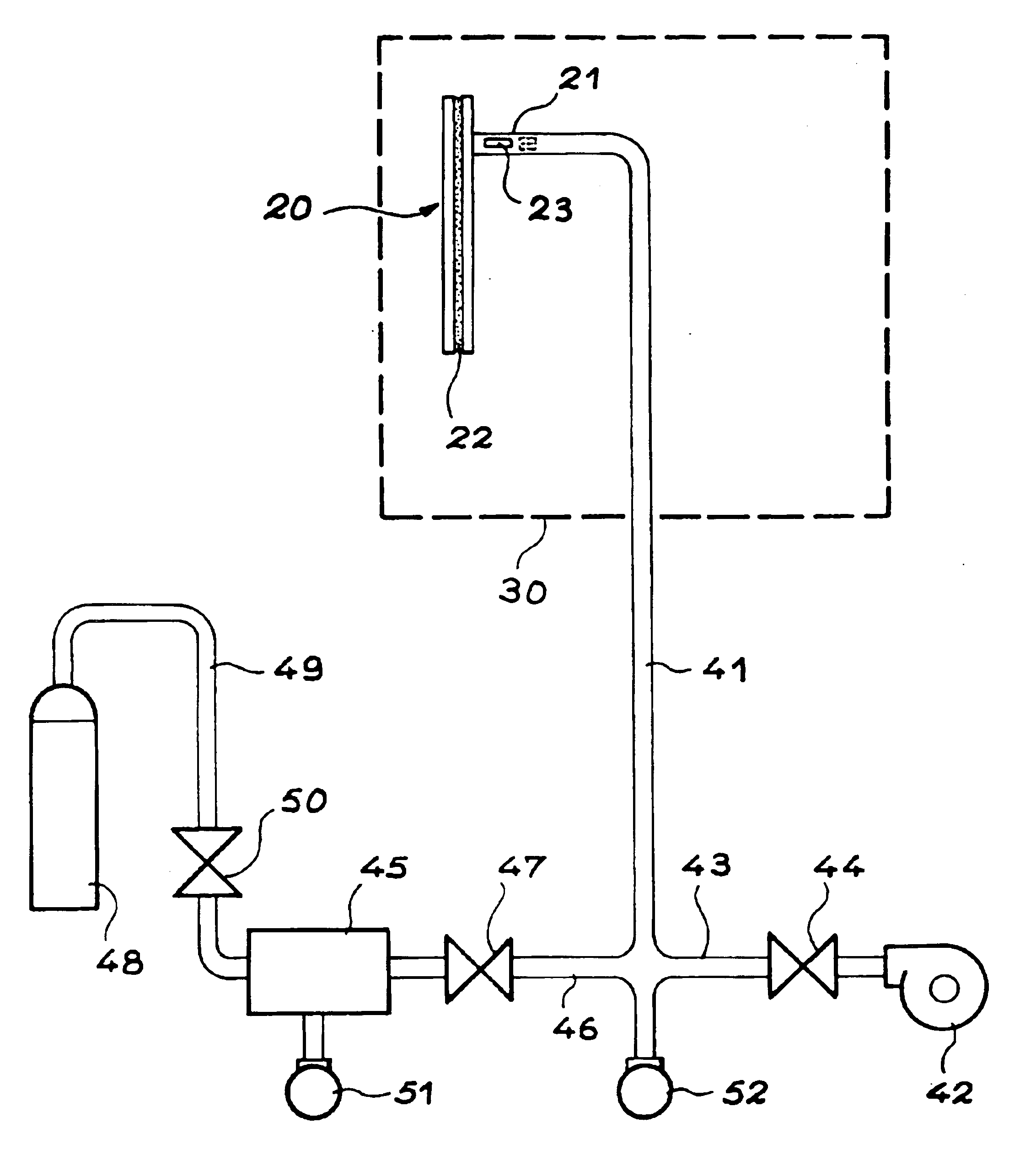
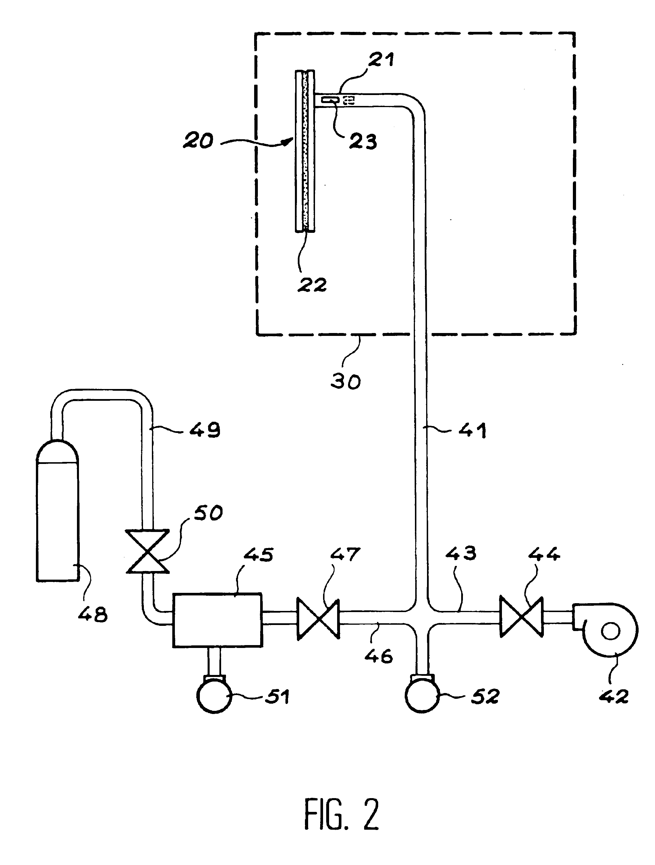
[0088]The device 20 is then placed in the zone 30 of the apparatus shown in FIG. 2, which allows it to be heated. The exhaust tube 21 is connected to a pipe 41, which allows it to be connected up to a turbo-molecular type vacuum pump 42 via a pipe 43, fitted with a valve 44 on one side and at the exit orifice by a gas reservoir 45, of known volume (for example 1.7 liters), via a pipe 46, fitted with a ...

example 2

[0095]According to a variation of example 1, NH3 may be introduced into the screen under dynamic conditions.

[0096]In order to do this, once the getter activation phase is finished, a partial pressure of NH3 is adjusted via valve 50, with valves 44 and 47 open.

[0097]The partial pressure of NH3 is preferably between 10−8 and 10−5 mbar. After a period of dynamic scanning lasting several minutes to several tens of minutes, the screen is isolated from the apparatus by sealing off the exhaust tube.

example 3

[0098]According to another implementation method, the screen may be assembled in an integral manner, in other words, the screen is de-gassed then sealed under vacuum or under a controlled atmosphere. The process is such that, after sealing, it remains under vacuum, or under a controlled atmosphere, unlike the previous case (examples 1 and 2) in which, after sealing, the screen is returned to atmospheric pressure and then re-evacuated and heated.

[0099]The following procedure may then be followed.

[0100]The various parts of the screen (strip bearing the cathode, strip bearing the anode, frit glass, getters, etc.) are placed in position under vacuum then heated to a temperature of around 300° C. to 450° C. for one or several hours. The getters may be placed in position either within the interior of the screen or in an external area such as a sealed off exhaust tube or getter box. During the heating stage, the anode may be laid flat against the cathode or maintained at a certain distance...


PUM


Abstract

The invention concerns a device comprising at least one field effect electron source within a sealed structure, which encompasses an internal space that contains a reducing gas whose purpose is to prevent oxidation of the emissive material of the electron source, whereby the reducing gas is a gas with the formula NxHy where x=1 or 2 and y=3 or 4, and which is advantageously under a pressure of between 10−8 and 10−1 mbar. It also concerns manufacturing processes for such a device and apparatuses for implementing these processes.

Description

[0001]This application is a national phase of PCT / FR00 / 01101 which was filed on Apr. 26, 2000, and was not published in English.TECHNICAL ASPECTS[0002]In a general manner, the present invention concerns a device that uses a field effect electron source (for example, a microdot device) and, more particularly, a field emission device, for example a flat, cathodo-luminescence display screen that is stimulated by field emission, or cold emission, using microdots. It also concerns the manufacture of such a device.[0003]More precisely, the invention involves creating a reducing atmosphere within the interior of the device in order to prevent the oxidation of the microdots (or other electron emitting elements) when the device is working.PRIOR TECHNICAL ART[0004]Microdot screens are flat cathode ray tubes that operate under vacuum. These screens comprise a cathode (notably made out of cathodic conductors, grids and microdots) and an anode (made out of conductors and luminophors). In order t...

Claims


Application Information

Patent Timeline
Patent Type & Authority Patents(United States)
IPC IPC(8): H01J29/94H01J29/00H01J9/395H01J9/38H01J9/385H01J31/12
CPCH01J9/395H01J29/94H01J2329/00
Inventor MEYER, ROBERTBORONAT, JEAN-FRAN.CEDILLA.OISLEVIS, MICHEL
Owner COMMISSARIAT A LENERGIE ATOMIQUE ET AUX ENERGIES ALTERNATIVES
Why Eureka
Try Eureka