

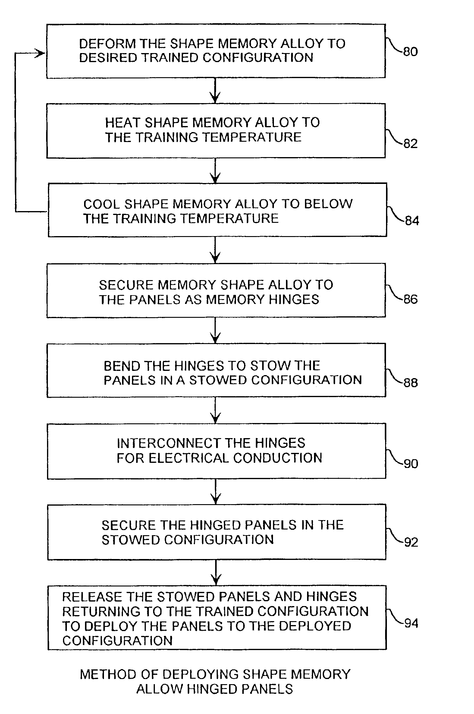
Shape memory metal latch hinge deployment method
a technology of latch hinges and memory metals, applied in the direction of hinges, wing accessories, manufacturing tools, etc., can solve the problems of insufficient power collection for onboard instruments and propulsion, extra apparatus for attitude pointing, and inability to provide enough power for body-mounted solar cells, etc., to achieve maximum stowage efficiency, less susceptible to vibration damage, and the effect of a small radius
- Summary
- Abstract
- Description
- Claims
- Application Information
AI Technical Summary
Benefits of technology
Problems solved by technology
Method used
Image

Examples
Embodiment Construction
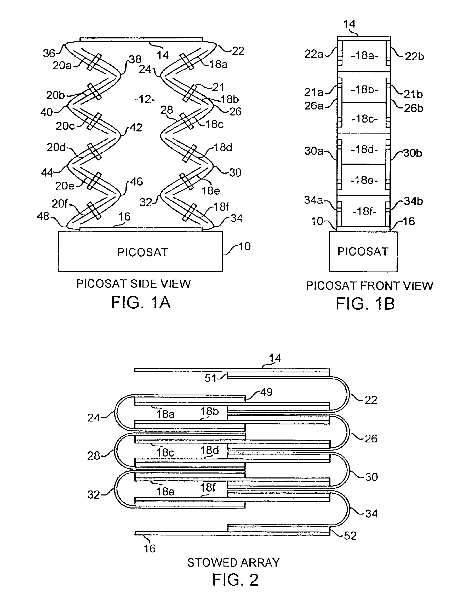
[0032]An embodiment of the invention is described with reference to the figures using reference designations as shown in the figures. Referring to FIGS. 1A, 1B and 2, a picosatellite 10 has a powerbox 12 including a top 14 and bottom 16. The powerbox 12 is formed by a plurality of rectangular panels including right side panels 18a, 18b, 18c, 18d, 18e, and 18f, collectively referred to as panels 18 and including left side panels 20a, 20b, 20c, 20d and 20f, collectively referred to as panels 20. For convenience, only the right and left sides of the powerbox 12 are shown, but it is understood that the powerbox 12 may further include identical front and back sides of panels, not shown. The right side panels 18 are interconnected together and to the top 14 and the bottom 16 by hinge pairs 22, 24, 26, 28, 30, 32 and 34, also respectively shown as hinges 22a and 22b, 24a and 24b, 26a and 26b, 28a and 28b, 30a and 30b, 32a and 32b, and 34a and 34b. The panels 18a and 20a are respectively co...
PUM
| Property | Measurement | Unit |
|---|---|---|
| Temperature | aaaaa | aaaaa |
| Electrical conductivity | aaaaa | aaaaa |
| Shape memory effect | aaaaa | aaaaa |
Abstract
Description
Claims
Application Information