Photocatalytic sheet or film and its manufacturing process

a technology of photocatalytic sheet and manufacturing process, which is applied in the field of manufacturing photocatalytic sheet, can solve the problems of slow production speed, low production speed, and slow production speed of the combination of coating, drying and optional baking process, which is described in jp 11047610, and achieves high production speed

Inactive Publication Date: 2005-05-10
FUJIFILM MFG EURO
View PDF13 Cites 79 Cited by
  • Summary
  • Abstract
  • Description
  • Claims
  • Application Information

AI Technical Summary

Benefits of technology

[0012]The object of the present invention is to provide a process for manufacturing a photocatalytic sheet at high production speeds.
[0013]It is also an important object of the invention to eliminate the drying process during manufacturing of said photocatalytic sheet.

Problems solved by technology

The combination of the coating, drying and optional baking processes, which is described in JP 11047610, is known to be slow.
As a result, the production speed becomes low.
The more drying and baling steps needed, the slower the production speed will be.
Another disadvantage of this process is that it costs relatively a lot of energy because first of all the photocatalytic particles have to be dispersed uniformly in the coating solution and secondly evaporating the solvent after coating in the drying or baling step.

Method used


Image

  • Photocatalytic sheet or film and its manufacturing process

Examples


example 1

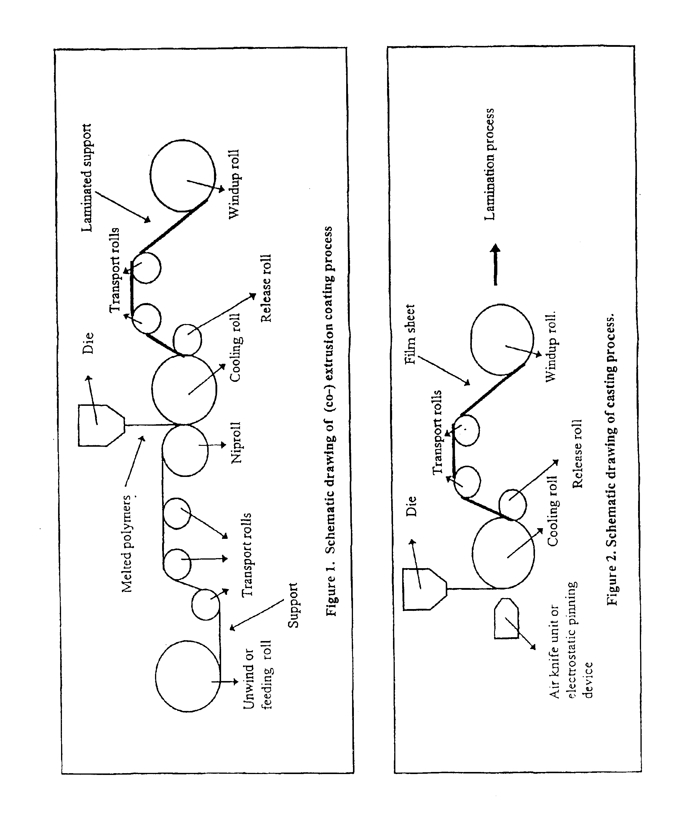
[0047]The following sheet was made by a co-extrusion process.

[0048]Hopper 1 was filled with a fluoropolymer masterbatch containing 15 wt % TiO2. The TiO2 was purchased from Ishihara, type St-41, and the fluoropolymer from Dyneon, type THV 220G. Hopper 1 was connected to a 2.5 inch single screw extruder 1.

[0049]Hopper 2 was filled with LDPE which had a Melt Flow Index of 2 (DSM grade) and was connected to a 2.5 inch single screw extruder 2.

[0050]These 2 screw extruders were combined in a two layer feedblock / coathanger die. The extrusion temperature was 210° C. The arrangement of the layers was done as such that the polymer from hopper 2 resided on the surface of base paper and the content of hopper 1 formed the most upper layer. The support which was a 166 g / m2 base paper, was fed via a number of rollers at a speed of 30 m / min, and was corona treated before entering the nip. In the nip, the melt polymer was ozone treated and was pressed by the cooling roll onto the base paper. Therea...

example 2

[0055]Hopper 1 was filled with a fluoropolymer masterbatch containing 30 wt % photocatalyst grade TiO2. The TiO2 was purchased from Ishihara, type St-41, and the fluoropolymer from Dyneon, type THV 220G. Hopper 1 was connected to a 2.5 inch single screw extruder 1.

[0056]In hopper 2, a 60 wt % master batch of pigment grade TiO2 in LDPE, was mixed together with fluoropolymer, THV and low density Polyethylene (LDPE) MFI-8 purchased from DSM in such away that the final concentration of pigment grade TiO2 in the hopper was 30 wt %, the amount of fluoropolymer was 30 wt % and the concentration of LDPE was 40 wt %. Hopper 2 was connected to a 2.5 inch single screw extruder 2.

[0057]In hopper 3 LDPE MFI-8 from DSM was stored and this hopper was connected to a 4.5 inch single screw extruder 3.

[0058]These 3 screw extruders are combined in a three layer feedblock / coathanger die. The melt temperature is 210° C. The arrangement of the layers was done as such that the polymer from hopper 3 resided...


PUM

PropertyMeasurementUnit
thicknessaaaaaaaaaa
thicknessaaaaaaaaaa
total thicknessaaaaaaaaaa

Abstract

The invention is directed to a photocatalytic sheet comprising a support, a photocalalytic layer comprising photocatalyst materials and binder, and at least one functional layer wherein said functional layer is in between said support and said photocatalytic layer, wherein said photocatalytic layer and said functional layer are brought on the support using extrusion coating technology or casting technology, as well as to a photocatalytic film sheet comprising: a photocatalytic layer comprising photocatalyst materials and binder, and at least one functional layer, wherein said film is formed by applying casting technology.

Description

FIELD OF INVENTION[0001]The present invention is directed to the process for manufacturing a photocatalytic sheet by using the extrusion coating technology.BACKGROUND OF THE INVENTION[0002]Recently there has been a lot of patents filed where the production and use of a photocatalytic coating containing a photocatalyst material such as titania (TiO2) is described. The said photocatalytic coating find its application in various field of technology, such as in the anti-fouling area [US 6013372] and in antibacterial applications [JP 11047610].[0003]When a photocatalyst, such as titanium dioxide, is subjected to photoexcitation by ultraviolet light (UV), water is chemisorbed on the surface of the titanium ion in the form of hydroxyl groups (OH—) as a result of the photocatalytic action. As a result, the surface of the material coated with TiO2 becomes very much hydrophilic. Due to said properties, a transparent film containing photocatalytic layer can be used as anti fogging material [US...

Claims


Application Information

Patent Timeline
Patent Type & Authority Patents(United States)
IPC IPC(8): B01J37/00B01J37/02B01J35/00B32B7/02B01J35/02
CPCB01J35/002B01J35/004B01J37/0215Y10S428/913Y10T428/257Y10T428/259Y10T428/258Y10T428/265Y10T428/25Y10T428/256Y10T428/3179Y10T428/3188
Inventor DISSE, LEOTODA, YUZOSATAKE, SEIMIGILLISSEN, HUUB
Owner FUJIFILM MFG EURO
Why Eureka
Try Eureka