Game system with graphics processor

a game system and graphics processor technology, applied in the field of computer system architectures, can solve the problems of high-resolution graphics, computational cost, difficult implementation of such graphics, and many limitations of game developers, and achieve the effect of hiding the main memory latency and reducing the amount of data

Inactive Publication Date: 2005-05-10
SONY COMPUTER ENTERTAINMENT INC
View PDF27 Cites 32 Cited by
  • Summary
  • Abstract
  • Description
  • Claims
  • Application Information

AI Technical Summary

Benefits of technology

[0018]In yet another aspect, the present invention provides all processors with a local cache memory. This architecture reduces the amount of data that is required to be transmitted on the relevant buses. In accordance with this aspect of the invention, the cache of the CPU is divided into an instruction cache and a data cache. The data cache first loads a necessary word from a cache line (sub-block ordering) and permits a hazard-free, cache-line hit while a previous load is still in process (hit-under-miss). The output from the cache is also buffered in a write back buffer. This structure allows write requests to be stored until the main bus is free.
[0019]A particularly preferred embodiment of the invention provides a scratchpad RAM that works as a double buffer for the CPU. In an application dealing primarily with computer graphics, most of the data written out of the primary processor will be in the form of display lists, which con

Problems solved by technology

The game developer is faced with many limitations.
Prior art game machines, however, make the implementation of such graphics difficult.
High resolution graphics are computationally expensive and difficult to render in the time required by a fast moving game.
Current graphics co-processors, if implemented at all in game consoles, have difficulty supplying the bandwidth necessary to render high resolution, real time graphics.
Prior art game machines also do not permit easy behavioral and physical modeling of game objects.
However, such modeling is computationally expensive, requiring many floating point oper

Method used


Image

  • Game system with graphics processor
  • Game system with graphics processor
  • Game system with graphics processor

Examples


Embodiment Construction

[0035]As discussed above, the present invention provides a computer system for providing high resolution computer graphics. The invention is particularly suited for interactive devices operating in real time or with other response time requirements (e.g., simulators and game machines). A preferred embodiment of the present invention, designed for a computer game machine, is described below.

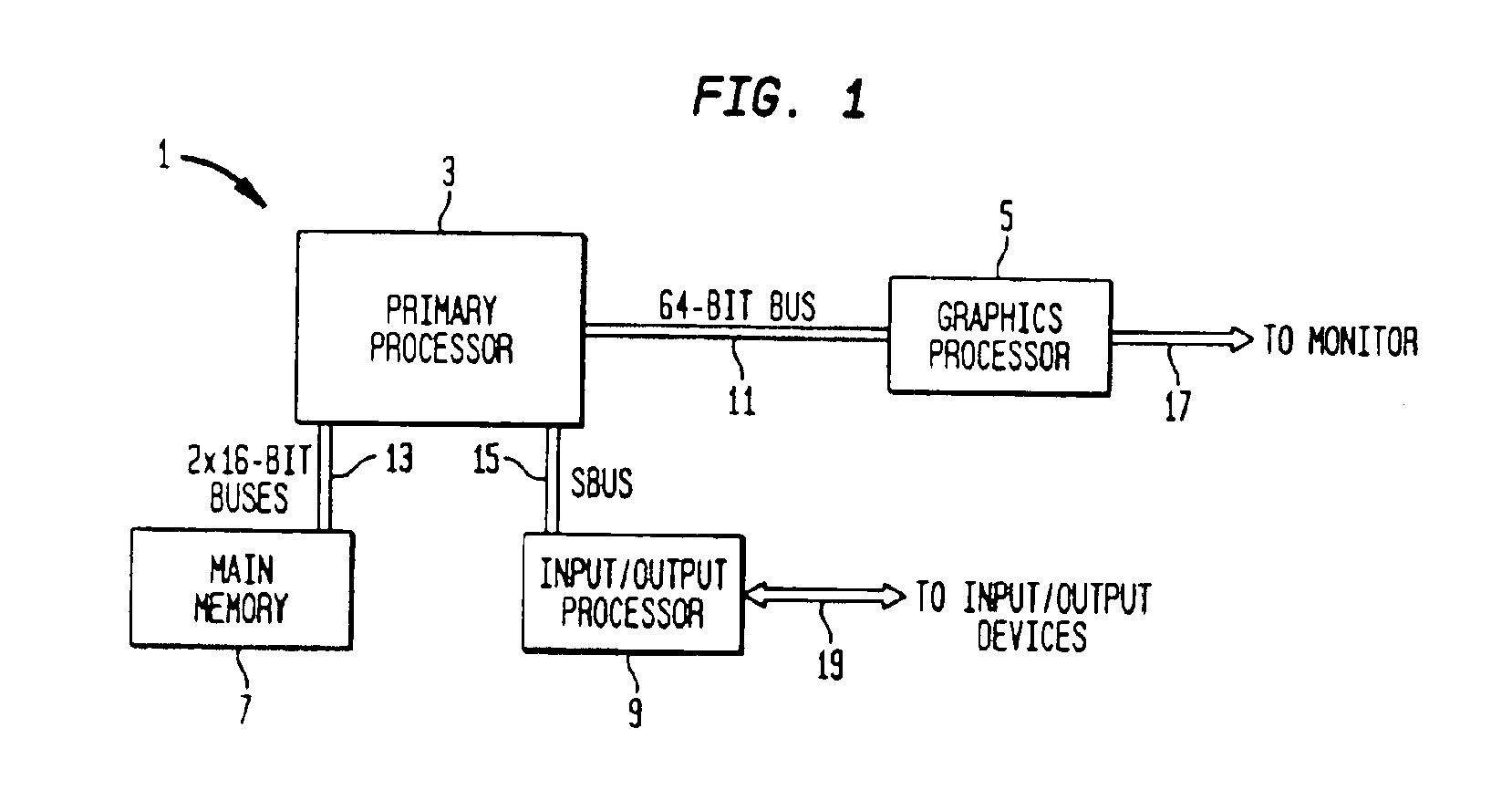
[0036]FIG. 1 is a block diagram of computer system 1. Computer system 1 consists primarily of primary processor 3, graphics processor 5, main memory 7 and input / output processor 9.

[0037]Primary processor 3 is a single 240 mm2 chip, created using a 0.25-micron photolithography process, with 10.5 million transistors which operates at 300 MHz. Primary processor 3 is connected to graphics processor 5 by a 64-bit bus 11 and to main memory 7 by a pair of 16-bit buses 13. Primary processor 3 is further connected to input / output processor 9 by a 32-bit SBUS 15. Graphics processor 5 is connected to a monit...


PUM


Abstract

The present invention relates to the architecture and use of a computer system optimized for the efficient modeling of graphics. The computer system has a primary processor and a graphics processor. The primary processor has two vector processor units within it, one which is closely connected to central processor unit. Simultaneously performing complex modeling calculations on the first vector processor and CPU, and geometry transformation calculations on the second vector processor, allows for efficient modeling of graphics. Furthermore, the graphics processor is optimized to rapidly switch between data flows from the two vector processors. In addition, the graphics processor is able to render many pixels simultaneously, and has a local memory on the graphics processor chip that acts as a frame buffer, texture buffer, and z buffer. This allows a high fill rate to the frame buffer.

Description

CROSS-REFERENCE TO RELATED APPLICATIONS[0001]This is a continuation of U.S. patent application Ser. No. 09 / 502,671 filed Feb. 11, 2000 U.S. Pat. No. 6,807,620, which is herein incorporated by reference.FIELD OF THE INVENTION[0002]The present invention relates to computer system architectures. More particularly, the present invention relates to the architecture and use of a computer system optimized for efficient modeling of graphics.BACKGROUND OF THE INVENTION[0003]High resolution, real time computer graphics are an important aspect of computer systems, particularly simulators (such as flight simulators) and game machines. Computer games, in particular, involve a great deal of computer graphics. Computer systems used as game machines, therefore, must handle far more computer graphics than a standard business computer used primarily for word processing or similar applications.[0004]The game developer is faced with many limitations. He or she often wants realistic, highly detailed gra...

Claims


Application Information

Patent Timeline
IPC IPC(8): G06T15/00
CPCG06T15/005A63F2300/203
Inventor OKA, MASAAKIOHBA, AKIOTANAKA, MASAYOSHI
Owner SONY COMPUTER ENTERTAINMENT INC
Why Eureka
Try Eureka