
Micro-structured optical fiber

a micro-structured, optical fiber technology, applied in the field of optical fibers, can solve the problems of reducing the efficiency of optical communication systems, unable to achieve significantly larger index contrasts in traditional fibre production processes, and waveguides with undoped cores with slightly lower refractive indexes, etc., to achieve strong positive group velocity dispersion, reduce coupling losses, and reduce the effect of coupling loss

Inactive Publication Date: 2005-05-10
CRYSTAL FIBRE AS
View PDF21 Cites 55 Cited by
  • Summary
  • Abstract
  • Description
  • Claims
  • Application Information

AI Technical Summary

Benefits of technology

[0070]A further advantage of the invention is that fibres according to the invention may make it possible to guide light in a mode, which is virtually circularly symmetric. A circular mode reduces coupling losses to standard fibres (because of a better mode overlap, as understood by those skilled in the art), and the circular mode can also be advantageous when considering bending losses (fibres without a preferred bending direction).
[0071]A further advantage of the present invention is that the structures of the present invention may allow guided solutions with a very low mode-index, said mode-index being defined as the propagation constant along the fibre divided by the wave-number. In principle, solutions with a mode-index of zero are possible (this is also possible with the fibres disclosed by Kawanishi et. al., but it is impossible with the fibres disclosed by Cregan et al., since no two-dimensional PBGs, with a propagation constant of zero, exist in pure silica / air structures). A localised solution with a mode-index close to zero propagates very slowly. The present inventors have realized that the group velocity of the guided mode, along the fibre, should be equal to or less than the free-space velocity of light multiplied by the mode-index, assuming the mode-index is less than unity. A guided mode with a mode-index of zero, therefore, in principle does not guide light along the fibre, while at the same time light cannot escape in the transverse direction due to the photonic bandgap effect. As a result light is in principle not propagating, or in more practical cases, the light is propagating with an unusual low group velocity. This, however, may only be obtained at discrete wavelengths. In practice, therefore, it is difficult to obtain fibres, which stop the light. The present inventors have realised that it is possible to utilize another quality of guided solutions with a low mode-index: Such solutions have very strong positive group velocity dispersion (said group velocity dispersion being defined as −λ / c d2{mode-index} / dλ2, where c is the free-space velocity of light and λ is the free-space wavelength) as well as a very large positive group velocity dispersion slope. Such a quality is unattainable using standard optical fibre technology. It should be noted that Kawanishi et al. discloses the possibility of guided solutions with zero or near zero mode-index, however, they do not disclose the importance of such solutions- namely the large group velocity dispersion and dispersion slope. Further, the fibres disclosed in the present application, may be designed to exhibit strong negative group velocity dispersion, at a desired wavelength.
[0072]A further aspect of the designs of the present invention is that it becomes possible to have guided solutions, which consist of only one polarization. Such polarizing fibres are of interest in systems, where the polarization must be known. Polarizing fibres may also provide means of avoiding birefringence in micro-structured fibres, since small deviations from a perfect structural symmetry may create birefringence in fibres like the one disclosed in Cregan et al.
[0073]It is a further advantage of the fibres disclosed in this application that the fibres may allow guidance of light within hollow cores within larger wavelength intervals than does the fibres disclosed by Cregan et al. This is because the PBGs of the structures of the present invention may inherently extend over larger wavelength regions than does the PBGs of two-dimensional structures, like the one disclosed in Cregan et. al (considering only the wavelength regions where the PBGs cover a mode-index of unity or less). For a discussion of the wavelength intervals, where guided modes exist within a hollow core in fibres like the ones disclosed in Cregan et. al, see e.g., Broeng et al., Pure and Applied optics, 1999, pp.477-482, and “Toward the development of practical photonic crystal fibers”, J. A. West, J. C. Fajardo, M. T. Gallagher, K. W. Koch, N. F. Borrelli, D. C. Allan, OSA Annual Meeting and Exhibit 2000, paper TuC1.
[0074]A further advantage of the present invention is that the fibres disclosed herein may allow guidance of light within hollow cores with a guided mode-index close to unity, within larger wavelength intervals than does the fibres disclosed by Cregan et al. This is because the PBGs of two-dimensional periodic structures are inherently smaller than the PBGs of the semi-periodic structures of the fibres of the present invention.
[0075]The present invention may be embedded in an article (which e.g., can be used in an optical fibre communication system) that comprises micro-structured fibre that is intended to guide light at a predetermined wavelength.

Problems solved by technology

These phenomena cause serious problems in optical communication systems.
It is a disadvantage of radial periodic fibres that significantly larger index contrasts cannot be obtained in a traditional fibre production process relying on doping of silica.
It is a disadvantage that this waveguide is not hollow but has an un-doped core with slightly lower refractive index than the cladding layers.
However, in large scale production of radial-periodic hollow waveguides for employment in telecommunication systems, index contrasts of this order of magnitude could turn out to be an insuperable difficulty of large-scale production of semi-periodic hollow waveguides, since it is expected to be very difficult to find the required dielectrics.
Moreover it is a disadvantage from an economical point of view that completely new production processes must be developed, if optical waveguides are no longer based on silica.
It is a disadvantage of the fibre described in EP 0 810 453 A1 and in U.S. Pat. No. 5,802,236, that only homogeneous material is used in the concentric circles forming the alternating relative high and low refractive index cladding, and as described above this results in limited intervals within which the refractive index values of the individual layers may be chosen.
It is further a disadvantage that the possibility of using a radial periodic cladding is not considered, such that the radial varying fibres disclosed in EP 0 810 453 A1 and in U.S. Pat. No. 5,802,236 will not allow photonic bandgap guidance of light.
It is, however a disadvantage that this fibre design (employing two different hole dimensions) does not have alternating concentrically distributed effective refractive index values, such as it is the case with the semi-periodic fibres disclosed in this application.
Although several segmented core designs are discussed in WO 00 / 16141, it is a disadvantage that these fibre designs does not have alternating concentrically distributed effective refractive index values throughout the cladding, such as it is the case with the semi-periodic fibres disclosed in this application, and although photonic bandgap guidance is mentioned, no detailed specifications besides the pitches in the range of about 0.4 μm to 5 μm are provided.

Method used


Image

  • Micro-structured optical fiber
  • Micro-structured optical fiber
  • Micro-structured optical fiber

Examples


Embodiment Construction

[0096]In the proceeding text, the invention will be described by way of example using selected preferred embodiments.

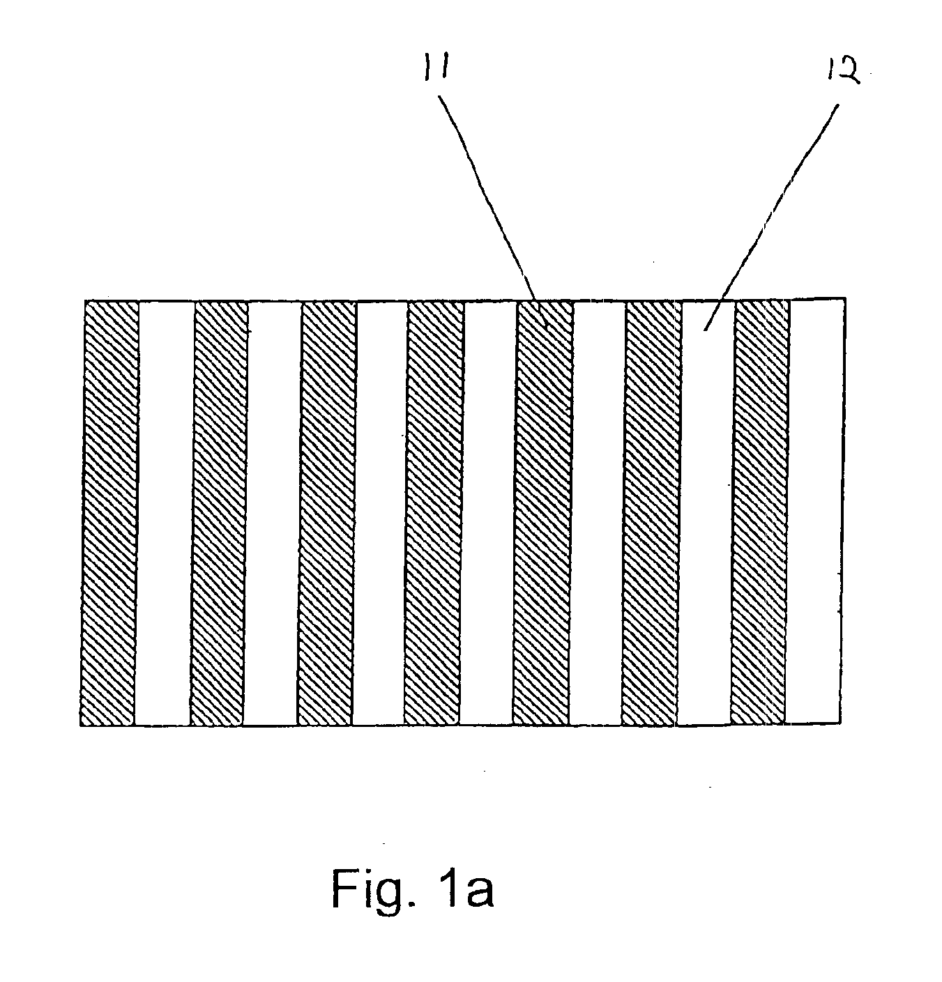
[0097]In the prior art, one-dimensional Bragg stacks as schematically shown in FIG. 1A, are known to exhibit photonic bandgaps. The Bragg stack consist of alternating layers of high index material (11) and low index material (12). Light incident directly on the stack is reflected completely by the Bragg-stack if the thickness of each layer corresponds to a quarter of a wavelength of the light. Such a Bragg stack is typically referred to as a dielectric mirror (since in principle all light is reflected), or it is termed a quarter wave stack. The wavelengths intervals, in which light is reflected are termed the photonic bandgaps of the Bragg stack at normal incidence.

[0098]Often Bragg stacks are designed for normal incidence, since the light will then not propagate in the invariant direction of the crystal. However, it is recognised that photonic bandgaps also exist for...


PUM

PropertyMeasurementUnit
Lengthaaaaaaaaaa
Lengthaaaaaaaaaa
Lengthaaaaaaaaaa

Abstract

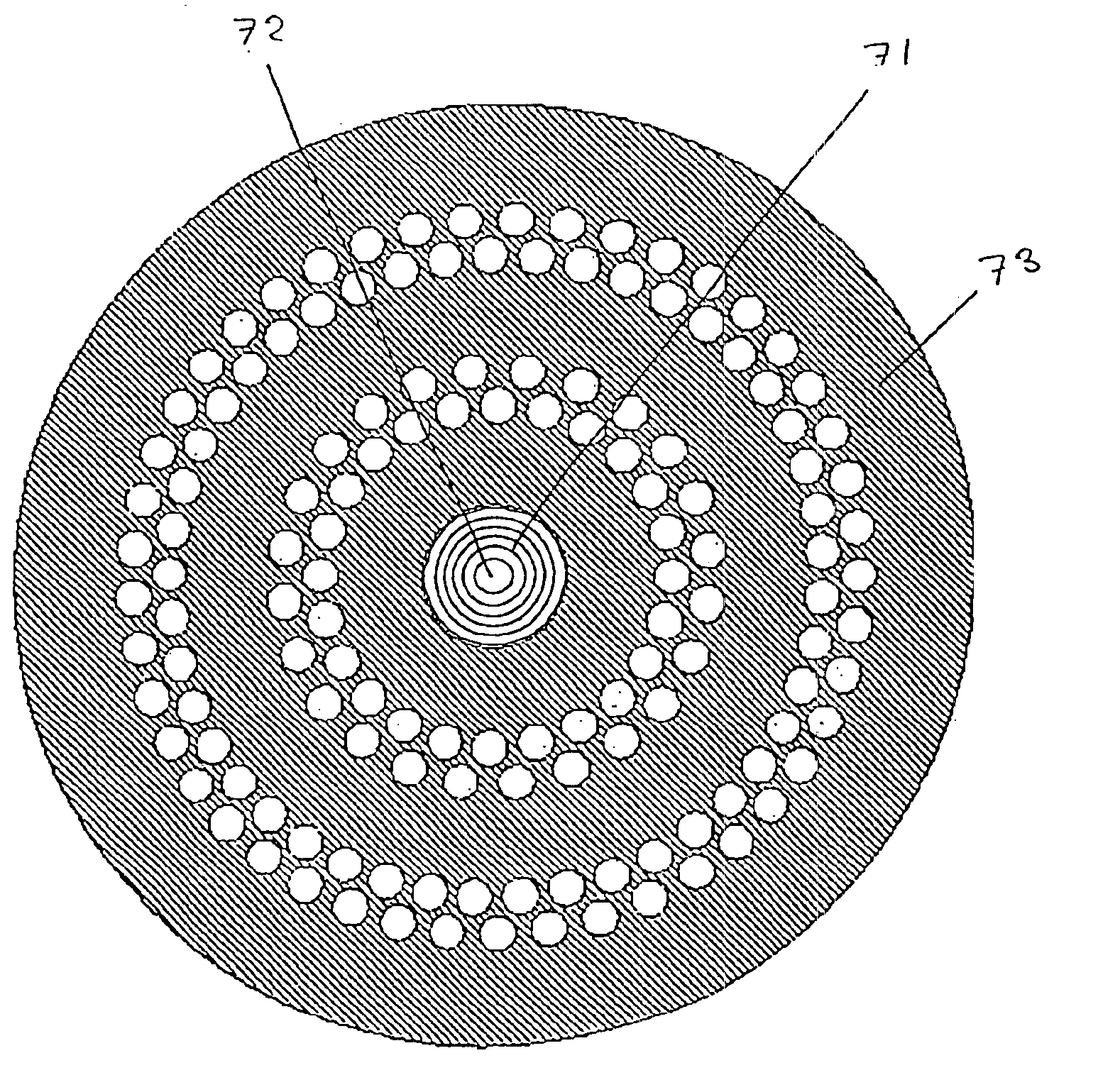
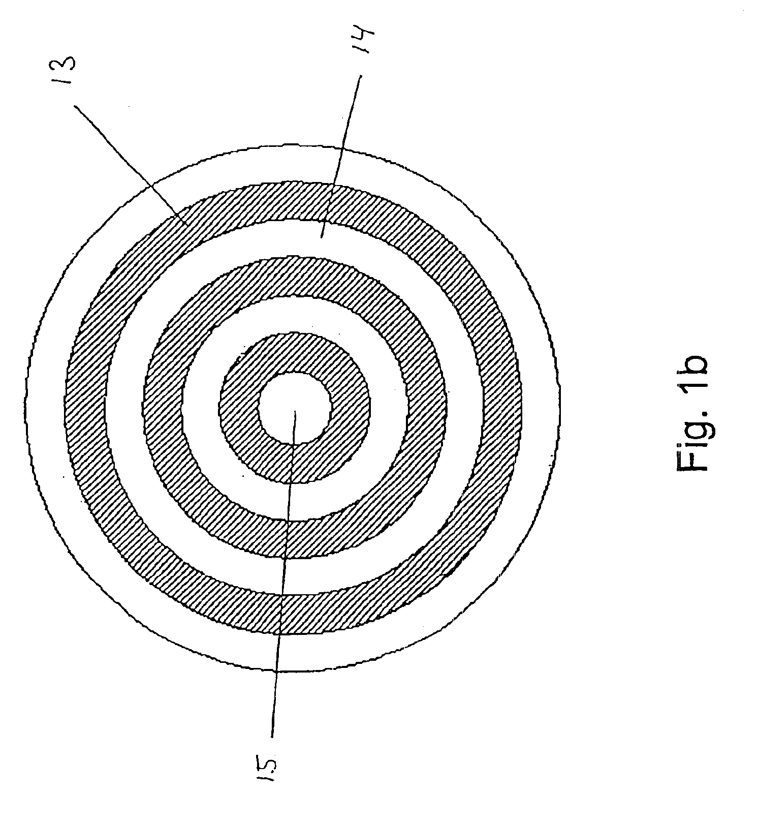
A microstructured fiber having a cladding comprising a number of elongated features that are arranged to provide concentric circular or polygonial regions surrounding the fiber core. The cladding comprises a plurality of concentric cladding regions, at least some of which comprising cladding features. Cladding regions comprising cladding features of a relatively low index type are arranged alternatingly with cladding regions of a relatively high index type. The cladding features are arranged in a non-periodic manner when viewed in a cross section of the fiber. The cladding enables waveguidance by photonic bandgap effects in the fiber core. An optical fiber of this type may be used for light guidance in hollow core fibers for high power transmission. The special cladding structure may also provide strong positive or negative dispersion of light guided through the fiber-making the fiber useful for telecommunication applications.

Description

[0001]This application is a 371 of PCT / DK01 / 00774 Nov. 20, 2001 which claims benefit of 60 / 287,728 May 2, 2001.FIELD OF THE INVENTION[0002]The present invention relates to electromagnetic waveguides, especially optical fibres, having micro-structures in cladding region(s).BACKGROUND OF THE INVENTION[0003]Optical fibre transmission systems are currently going through a tremendous development, and numerous new applications appear within the area of multi-channel optical communications. These new applications are typically based on new functionalities in the optical fibre components, and one of the interesting developments within the past 4-5 years has been the appearance of “photonic crystal” or “photonic bandgap” fibres as described in T. A. Birks et al., Electronics Letters, Vol.31 (22), p.1941 (October 1995), and J. C. Knight et al. Proceedings of OFC, PD3-1 (February 1996). Photonic bandgap fibre typically involves a dielectric structure with a refractive index that varies periodi...

Claims


Application Information

Patent Timeline
IPC IPC(8): C03B37/02C03B37/012C03B37/027G02B6/02
CPCC03B37/0122C03B37/02781C03B37/0279G02B6/023G02B6/02328G02B6/02347G02B6/02357G02B6/02361C03B2203/14C03B2203/16C03B2203/42G02B6/02385C03B2205/10C03B2205/08
Inventor LIBORI, STIG EIGIL BARKOUBROENG, JESBJARKLEV, ANDERS OVERGAARDRASMUSSEN, CHRISTIANKNUDSEN, ERIK
Owner CRYSTAL FIBRE AS
Learn More