Circuit and method for measurement of battery capacity fade

a technology applied in the field of circuit and measurement method for measuring battery capacity fade, can solve the problems of long periods of relative inactivity, inconvenient use, and the inability of most battery operated systems such as personal digital assistants (pdas), to provide continuous heavy load on the battery, and achieve accurate indication of remaining run-tim

Inactive Publication Date: 2005-05-10
TEXAS INSTR INC
View PDF6 Cites 142 Cited by
  • Summary
  • Abstract
  • Description
  • Claims
  • Application Information

AI Technical Summary

Benefits of technology

[0015]It is an object of the present invention to provide an improved battery measurement system and method that provides an accurate present estimate of remaining batter

Problems solved by technology

However, it is often inconvenient to the user to ensure both that the battery is initially fully charged and then is immediately fully discharged as is required for the prior methods of determining battery capacity fade.
Instead, most battery operated systems such as electronic notebooks, laptop computers, mobile phones, personal digital assistants (PDAs) and the like do not provide continuous heavy loading on the battery, but instead are characterized by short periods of high current drain on the battery and long periods of relative inactivity in “off” or “standby” conditions.)
Consequently, battery capacity fade usually is not properly determined during the long intervals between the rare occurrences wherein the battery is fully discharged immediately after being fully charged.
Therefore, the accuracy of the terminations of remaining run-time become less and less accurate as the battery “ages”.
Although certain corrections of battery capacity calculations can be performed numerically using previously measured data representing the dependency of battery capacity fade based on the number of prior charge/discharge cycles of the battery and the amount of total cumulative charge that has passed through the battery, such corrections require time-consuming collection of data that is specific to each particular model or type of battery.
Furthermore, such data usually is quite imprecise because battery capacity fade is heavily dependent on the various conditions o

Method used


Image

  • Circuit and method for measurement of battery capacity fade
  • Circuit and method for measurement of battery capacity fade
  • Circuit and method for measurement of battery capacity fade

Examples


Embodiment Construction

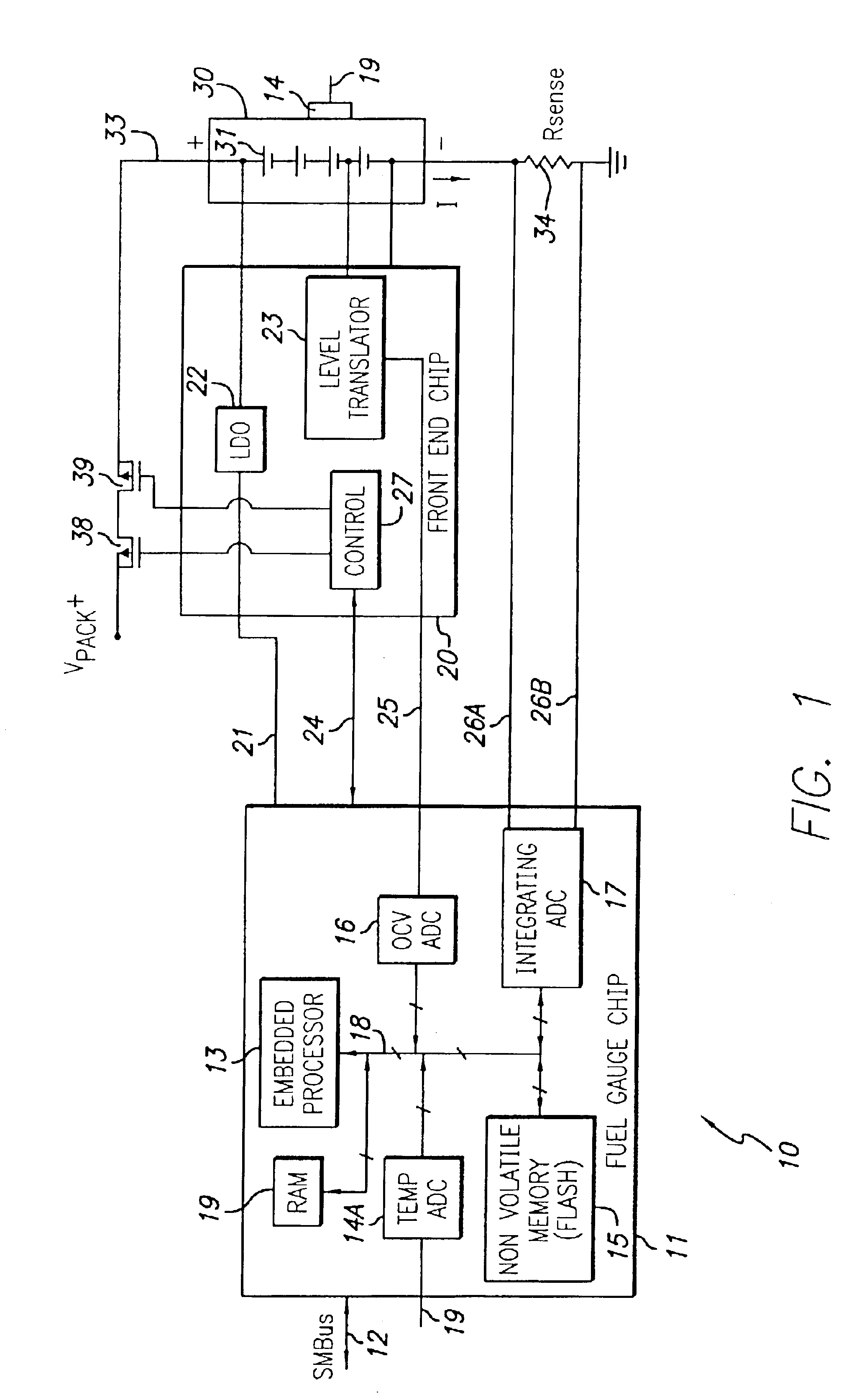
[0031]Referring to FIG. 1, a “battery fuel gauge system”10 includes a “battery fuel gauge” integrated circuit chip 11 that includes an embedded processor 13 coupled by a bidirectional digital bus 18 to a temperature sensor circuit 14, a nonvolatile memory 15, a random access memory (RAM) 19, an analog-to-digital converter (ADC) 16, and an integrating analog-to-digital converter 17. The temperature sensor circuit 14 is coupled to an external sensor 19 which is directly attached to the battery 30 shown in FIG. 1. Nonvolatile memory 15 could be a conventional flash memory, ADC 16 and ADC 17 both can be conventional analog-to-digital converters, and embedded processor 13 can, for example, be a commercially available 8 MHz processor having an 8-bit central processing unit (CPU) and a RISC architecture. Various suitable embedded processors that are commercially available can be utilized. For example, the Assignee's MSP430 microprocessor is capable of performing the necessary computations,...


PUM


Abstract

The remaining run-time (t_rem) of a battery is determined independently of the condition of the battery and the amount of load on the battery by obtaining the value of a present total zero-current capacity (Qmax) of the battery based on relaxed-battery OCV values measured just before and just after a charging or discharging cycle. A current through the battery is integrated to determine a transfer of charge (Q) from the battery, and a value of total run-time (t_total) that would be required to reduce the open circuit voltage of the battery to a predetermined lower limit (Vmin) is determined. The remaining run-time (t_rem) is determined by subtracting the duration of the integrating from the total run-time (t_total).

Description

[0001]This application claims priority under 35 USC § 119 of provisional application Ser. No. 60 / 437,470, filed Dec. 29, 2002.BACKGROUND OF THE INVENTION[0002]The present invention relates generally to circuits and techniques for providing an accurate indication of the present “depth of discharge” (DOD) of a rechargeable battery, and particularly to such circuits and techniques that avoid the need to fully charge and then immediately fully discharge the battery in order to obtain an accurate DOD value in spite of fade of the full charge capacity of the battery in the course of repeated use.[0003]It is well known that a no-load measurement of the terminal voltage of a battery (or cell thereof) is an accurate indication of its DOD if the battery has been in a no-load condition for a substantial amount of time, which may be from approximately half an hour to several hours. It also is well-known that an estimate of the “remaining run-time” of a battery operated device is dependent on ac...

Claims


Application Information

Patent Timeline
IPC IPC(8): G01R31/36G06F19/00H01M10/48H01M50/569
CPCG01R31/361H01M10/482G01R31/3648G01R31/3828Y02E60/10H01M50/569
Inventor BARSOUKOV, EVGENIJPOOLE, DAN R.FREEMAN, DAVID L.
Owner TEXAS INSTR INC
Why Eureka
Try Eureka