System for and methods of operating diesel engines to reduce harmful exhaust emissions and to improve engine lubrication

a technology of engine lubrication and exhaust emissions, which is applied in the direction of machines/engines, mechanical equipment, and non-fuel substance addition to fuel, etc., can solve the problems that the engine combustion system alone cannot meet future diesel emissions standards, and the toxic to human health of finely dispersed particles, etc., to facilitate dpf regeneration, reduce nox formation, and anti-wear properties

Inactive Publication Date: 2005-05-17
RIM JULIUS J
View PDF20 Cites 47 Cited by
  • Summary
  • Abstract
  • Description
  • Claims
  • Application Information

AI Technical Summary

Benefits of technology

[0022]The system according to the invention may incorporate an improved engine lubricating oil composition that facilitates DPF regeneration, and also has anti-wear properties. The present invention also relates to a method of using such engine lubricating oil in diesel engines.
[0023]The emissions-reduction system according to the present invention also provides an optional method of supplying water vapor and a catalyst to a diesel engine's intake manifold, via the EGR system, to reduce NOx formation from diesel exhaust gases, without causing an engine wear problem.
[0024]It has been discovered that the use of an engine lubricant oil additive composition added to engine oil in the oil sump, part of which is later transferred to the fuel tank, extends the useful life of the diesel particulate filter in the exhaust system by lowering the ignition temperature of PM colleted by DPF during regeneration, while also providing superior lubricating properties for diesel engines equipped with a DPF system according to the present invention. The additive composition hereof includes one or more organo-metallic compounds of Cu, Ce, Pb, Mn, Zn, in a range of about 0.05% to 10%, a preferred range of about 0.1% to about 6%, or a most preferred range of about 0.1% to about 2% by weight of the total weight of the oil.
[0025]The present invention also provides an alternate method of using a fuel-borne catalyst (FBC) for diesel engines equipped with DPF, by mixing a predetermined amount of catalyst into engine oil in the engine oil sump, and subsequently feeding a controlled amount of such catalyst-loaded oil from the engine oil sump into the fuel tank. This lowers the ignition temperature of PM collected by the DPF.

Problems solved by technology

A problem exists because concurrent reduction of both PM and NOx from diesel engines is difficult, due to a well-known trade-off relationship between the production of these two emission products in the diesel combustion process.
However, it must be recognized that the engine combustion system alone cannot meet future diesel emissions standards, particularly with regard to PM and NOx.
Such finely dispersed particles are believed to be toxic to human health.
DPF technologies, including CDPFs, are generally effective in greatly reducing emissions of PM, but fail to reduce NOx from diesel emissions.
However, water-addition methods including the EGR process are not widely practiced in diesel engine combustion systems, because of concerns about possible engine wear problems caused by the break-down of the protective film of lubricating oil by contact with water in critical rubbing metal surfaces, such as the surfaces between piston rings and cylinder walls and valve bearings, etc.
The use of diesel engine lubricating oil containing iron compounds, as shown in U.S. Pat. No. 4,946,609, is not always sufficient for inducing catalytic regeneration of the collected PM in all driving modes.
However, burning used engine oil in diesel fuel, by the methods disclosed in these patents, emits more air-pollutants, and is not allowed in some countries without use of DPF system.

Method used


Image

  • System for and methods of operating diesel engines to reduce harmful exhaust emissions and to improve engine lubrication
  • System for and methods of operating diesel engines to reduce harmful exhaust emissions and to improve engine lubrication
  • System for and methods of operating diesel engines to reduce harmful exhaust emissions and to improve engine lubrication

Examples


example 1

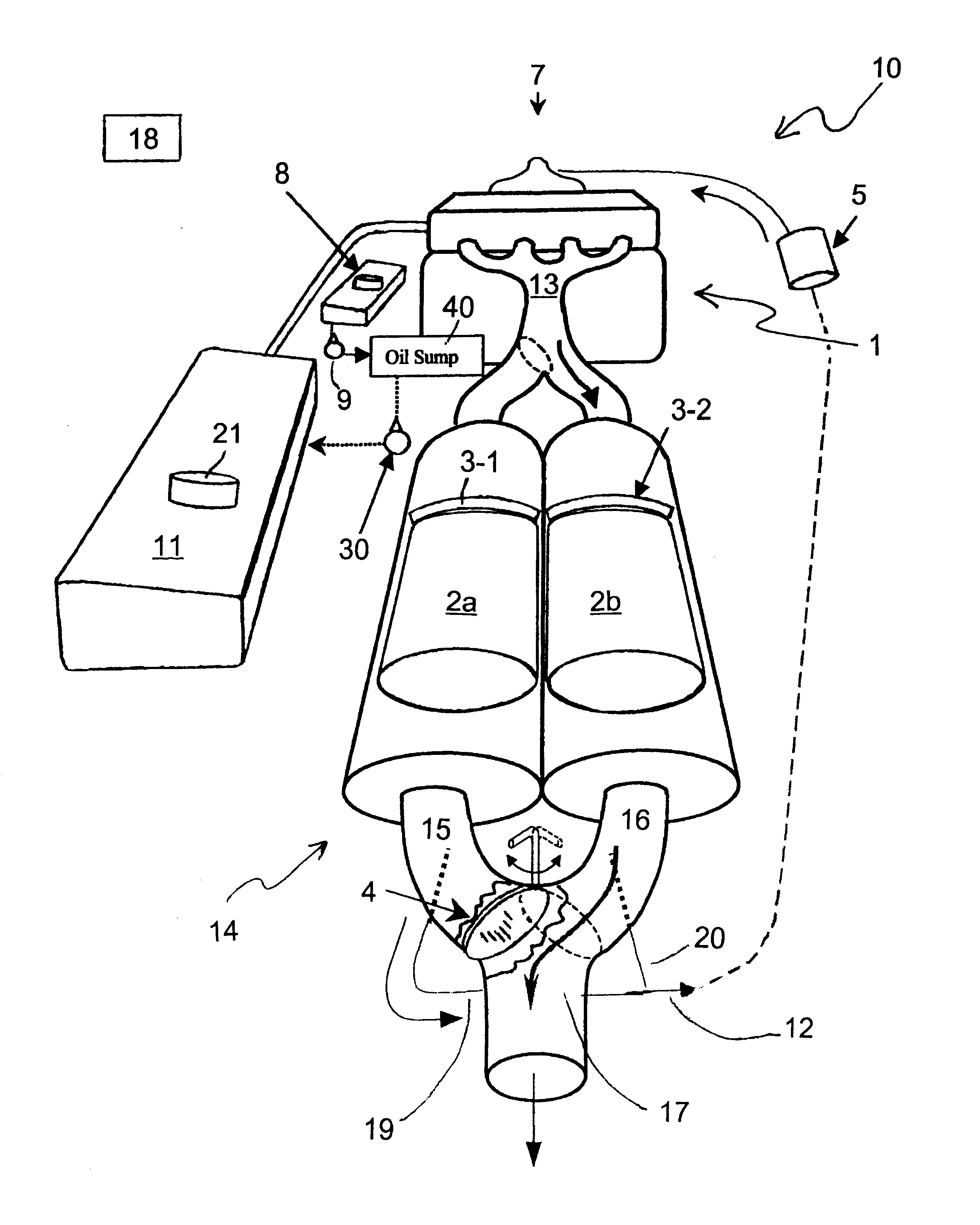
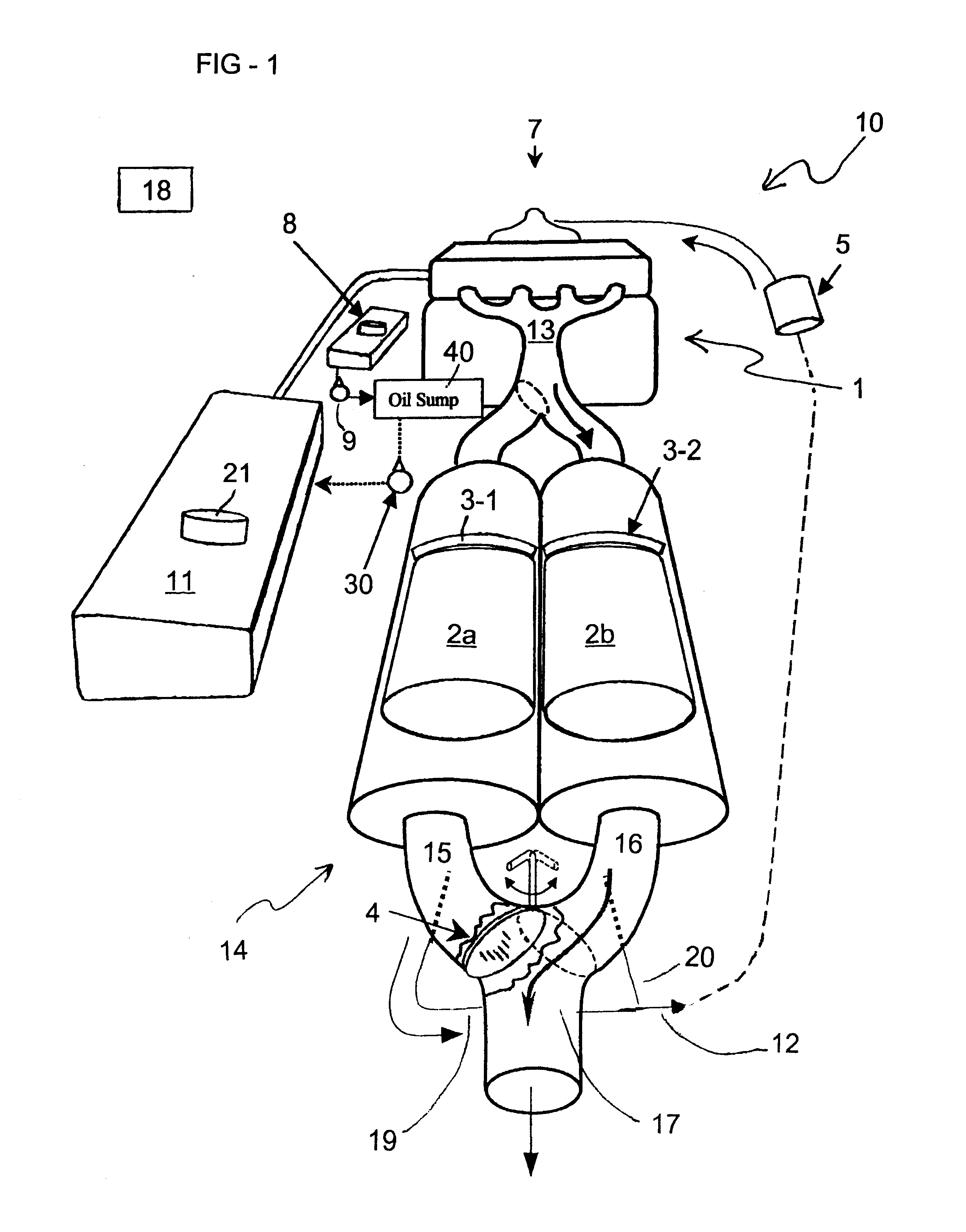
[0048]Referring to FIG. 1, dual filters, with each filter made of Coming Diesel particulate filter, 5.66 in. diameter×6 in. long, 100 cells / sq. in. was canned in the conventional manner, with an electric coil installed in front of the filter.

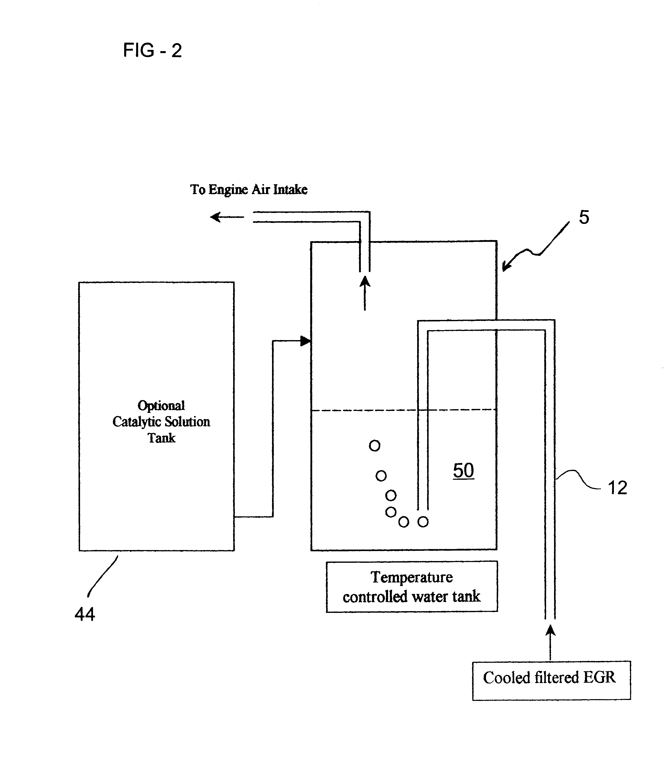
[0049]The flow of exhaust gases and EGR gas was controlled by the diverter valve in the exhaust system, as shown in FIG. 1. EGR gases from the DPF are fed into the air-intake port via the step of bubbling through the water solution in the EGR-accumulator tank, which is filled with 2 liters of water containing 50 grams of copper acetate, and a trace of ethylene glycol to prevent freezing at cold temperatures.

[0050]All the features of this invention process were installed on a Mercedes 300 D with a diesel engine, 3.0 liters of engine displacement. The test fuel was a regular diesel fuel with 300-400 ppm sulfur present in the fuel. The engine oil used was a regular engine lubricant, 10W-40 viscosity suitable for diesel engines, to which the engine...


PUM


Abstract

A Diesel engine anti-wear lubricant oil additive composition that includes organo-metallic compounds of Cu, Ce, etc., is used to catalytically burn-off diesel particulate matter (PM) collected by diesel particulate filter (DPF). A fuel borne catalyst (FBC) of Cu,Ce,Fe etc., required for regenerating the DPF is made by blending a predetermined quantity of used engine oil, removed from the engine crankcase oil system, with fuel in the fuel tank of a diesel engine equipped with DPF and EGR systems. A method of fumigating water and catalytic compounds of Cu, Fe, Ce, etc., into the air-intake system of a diesel engine in the EGR gases from the DPF or air, to reduce both PM and NOx emissions from a diesel engine, with improved engine lubrication performance, is also disclosed.

Description

BACKGROUND OF THE INVENTION[0001]1. Field of the Invention[0002]The present invention relates to an improved method of operating diesel engines equipped with Diesel Particulate Filter (DPF) and Exhaust Gas Recirculation (EGR) systems, to reduce emissions of Particulate Matter (PM), unburned Hydrocarbons (HC) and Oxides of Nitrogen (NOx) from diesel engines. More specifically, the present invention is related to a catalytic DPF system that improves emissions by filtering exhaust, and which regenerates the filter by burning off collected PM therefrom. This invention is further related to a method of reducing NOx through the use of a cooled EGR gas, as well as introduction of water into a diesel engine combustion system. The present invention also relates to an engine anti-wear lubricating composition, and to a method of employing such engine lubricant oil in internal combustion engines, including diesel engines.[0003]2. Description of the Background Art[0004]In efforts to reduce globa...

Claims


Application Information

Patent Timeline
Patent Type & Authority Patents(United States)
IPC IPC(8): F01N3/023F01N3/025F02M25/07F02M25/00F01N7/00F01N7/04F02B3/00F02D9/04F02D9/00F02B3/06F01N13/04
CPCF01N3/0253F01N3/0256F02M25/00F02M25/074F02M25/0742F02M25/0743F01N13/011C10M2207/10F02M25/0224C10N2210/01C10N2210/02C10N2210/04C10N2210/08C10N2230/38C10N2230/50C10N2240/102F01N2390/00F01N2410/04F01N2430/04F02B3/06F02D9/04F02M25/0718F02M25/0727Y02T10/121C10M2207/16F02M26/15F02M26/23F02M26/35F02M26/36F02M26/37C10N2010/14C10N2010/08C10N2010/02C10N2010/04C10N2030/38C10N2030/50C10N2040/252C10N2010/16F01N3/10F01N3/00F02M25/06
Inventor RIM, JULIUS J.
Owner RIM JULIUS J
Why Eureka
Try Eureka