Self-anchoring fiber block system

a fiber block and fiber block technology, applied in artificial islands, construction, marine site engineering, etc., can solve the problems of increasing the danger of flash flooding, and increasing the pollution level of unfiltered runoff, so as to prevent soil erosion, facilitate installation, and promote vegetation growth

Inactive Publication Date: 2005-05-17
SANTHA B LANKA
View PDF21 Cites 56 Cited by
  • Summary
  • Abstract
  • Description
  • Claims
  • Application Information

AI Technical Summary

Benefits of technology

[0011]The invention is a self-anchoring fiber block system that can be positioned along a shoreline or waterway bank to stabilize the shoreline or waterway bank by preventing soil erosion, supporting the soil behind the system (i.e., the soil on the other side of the system from the water) and promoting growth of vegetation. The structure is easy to install, made of natural materials, friendly to wildlife habitat, protects the shoreline or waterway bank against erosion from its installation onward, promotes growth of vegetation along the shoreline or waterway bank, and can be anchored in place with few, if any, separate anchoring structures. Because the fiber block system is made of natural materials and controls erosion so effectively, it may be installed closer to the water to protect as much of the shoreline or waterway bank from erosion as is desired. The natural materials of which the fiber block system is made can also support vegetation growth in the fiber block system itself. Thus, vegetation can be implanted in the fiber block system itself in a manner that protects the vegetation from forces of erosion and accelerates its growth along the shoreline or waterway. The fiber block system can be made of interlocking fiber block segments that connect easily and without the need for specialized tools or connecting hardware. The fiber block system also protects the bare soil behind (in relation to the water) the structure from erosion because, among other reasons, it is thick enough to function as a barrier between the soil and the water. Thus, the fiber block system promotes growth of vegetation in the soil behind the structure also. Because the fiber block segments can be stacked atop each other, the installer can construct an artificial bank of a chosen elevation to further control the path of water flowing in a waterway or shape the shoreline. The embodiment of the fiber block system with a fiber block segment having a rectangular cross section has an improved ability to retain soil behind it because of the increased contact area between the bottom of the rectangular fiber block segment when compared to a fiber block system using a fiber block segment having a circular cross section. Nonetheless, a fiber block system using fiber block segments with a circular cross section can also be used if desired. These and other advantages of the invention will become apparent to a skilled artisan based on his or her review of the following description and the accompanying illustrations.
[0014]The fiber blocks defining the water side faces of fiber block segments enable construction of an erosion control system of a substantially constant height. In general, the slope angle of the bank can be varied by moving the layers of the fiber block segments relative to each other. The fiber block segments are installed over an extended length along the shoreline or waterway bank by connecting fiber block segments end-to-end and mating the male end of one fiber block segment to the female end of an adjacent fiber block segment to create a continuous erosion control system along the shoreline or waterway bank. The pouch at the female end of the fiber block segment securely holds an inserted male end of the adjacent fiber block segment and maintains the continuity and the structural integrity of the system. The weight of soil on top of the anchor portions also keeps the fiber block segments in place. Other arrangements of the fiber block system are described below.

Problems solved by technology

This unfiltered runoff harms the environment by increasing pollution levels in the waterways within the watershed.
The increased runoff also increases the danger of flash flooding and flows through the watershed at increased velocities.
The faster the runoff flows through existing waterways and the higher the volume of the runoff, the more the runoff erodes the banks of the waterways and the more the runoff harms the ecosystem of the watershed.
Additionally, severe washouts along the banks of the eroded waterway may damage property located near the banks.
However, this method completely destroys the localized ecosystem along the bank because it requires completely removing the vegetation growing along the bank.
Along with the disadvantages inherent in concrete lining, the use of riprap alongside waterways can block water flow during severe flow conditions if pieces of the riprap move from their intended locations.
Additionally, both concrete and riprap are expensive to install on waterway banks and shorelines.
Although various methods described in Bestmann's patents involve the growth of vegetation as a mechanism for slowing or eliminating erosion on waterway banks and shorelines, they all have a common problem in installation of the objects.
Because Bestmann's wooden stakes are submerged under water but not buried in the soil, their buoyancy causes them to loosen and eventually work free from their anchoring position, which can cause the erosion control system to fail.
Bestmann's wooden stakes can also rot and lose their structural integrity within short period of time when compared to the coir material used in much of the remaining structure in Bestmann's erosion control systems.
Bestmann's wooden stakes also require extensive labor, which increases the costs associated with using Bestmann's erosion control systems.
Bestmann's steel anchoring structures do not float or rot quickly, but they also require extensive labor.
Bestmann's erosion control systems also suffer the disadvantage of having structurally weak connections between the erosion control objects when the objects are installed over an extended length to cover long sections of a shoreline or bank.
The shift in alignment exposes the soil between the objects to water and thus erosion.
Use of these blocks in waterway banks and shorelines to stop erosion is not an environmental friendly approach.
Moreover, these blocks are complicated to handle during installation.
Once removed, these plastic blocks are very difficult to dispose of properly because they are not biodegradable.
Moreover, environmental regulations make using these plastic blocks in environmentally sensitive wetland and wildlife habitat difficult if not impossible.
These anchors are expensive and their installation is labor intensive.
Moreover, synthetic nets of the type described by Brown can entrap and kill reptiles, birds, and fish leading to trap them and eventually kill them.
Therefore, it is difficult, if not impossible to use these materials in environmentally sensitive wetland and wildlife habitat promoting areas.
Because Bourg's erosion control system suffers all the problems inherent with the concrete lining method described earlier, it is inappropriate to use them along environmentally sensitive watershed and wildlife habitat areas.
Therefore, placing soil cement on a waterway bank is expensive and time consuming.
Moreover, Perslow, et al's soil cement waterway bank lining system is not friendly to ecosystem along the waterway bank.
Soil cement does not promote growth of vegetation and it does function as a natural wildlife habitat.

Method used


Image

  • Self-anchoring fiber block system
  • Self-anchoring fiber block system
  • Self-anchoring fiber block system

Examples


Embodiment Construction

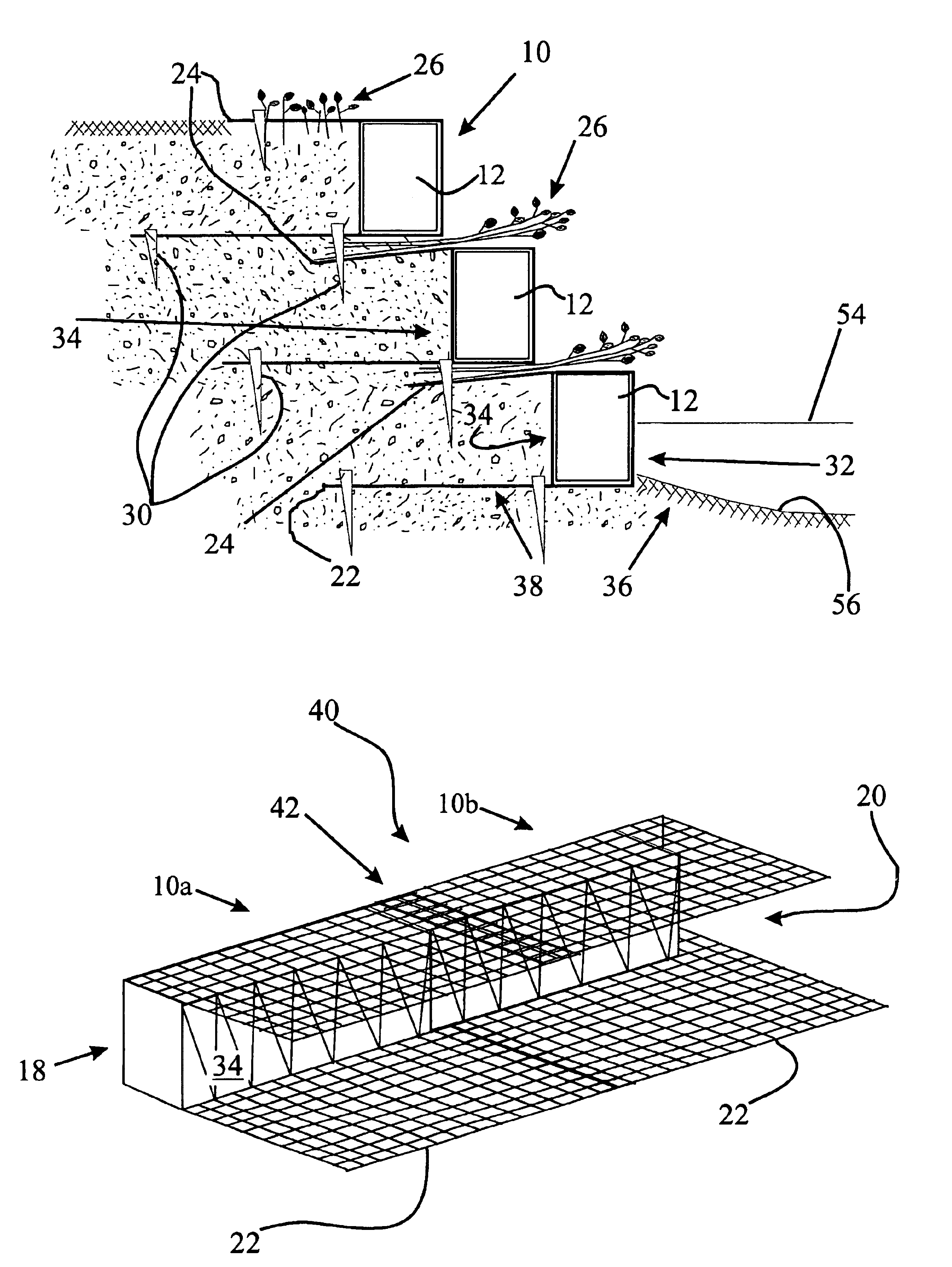
[0036]This application refers in detail below to the exemplary embodiments of a self-anchoring fiber block segment 10 according to the invention, which are illustrated in the accompanying drawings. The fiber block segment 10 can be used as a component of a fiber block system 40 to stabilize a shoreline or waterway bank by providing support for and preventing erosion of the soil behind the fiber block system 40 (on the other side of the fiber block system 40 from the side exposed to water). Wherever possible, the application uses the same reference numbers throughout the drawings to refer to the same or similar items.

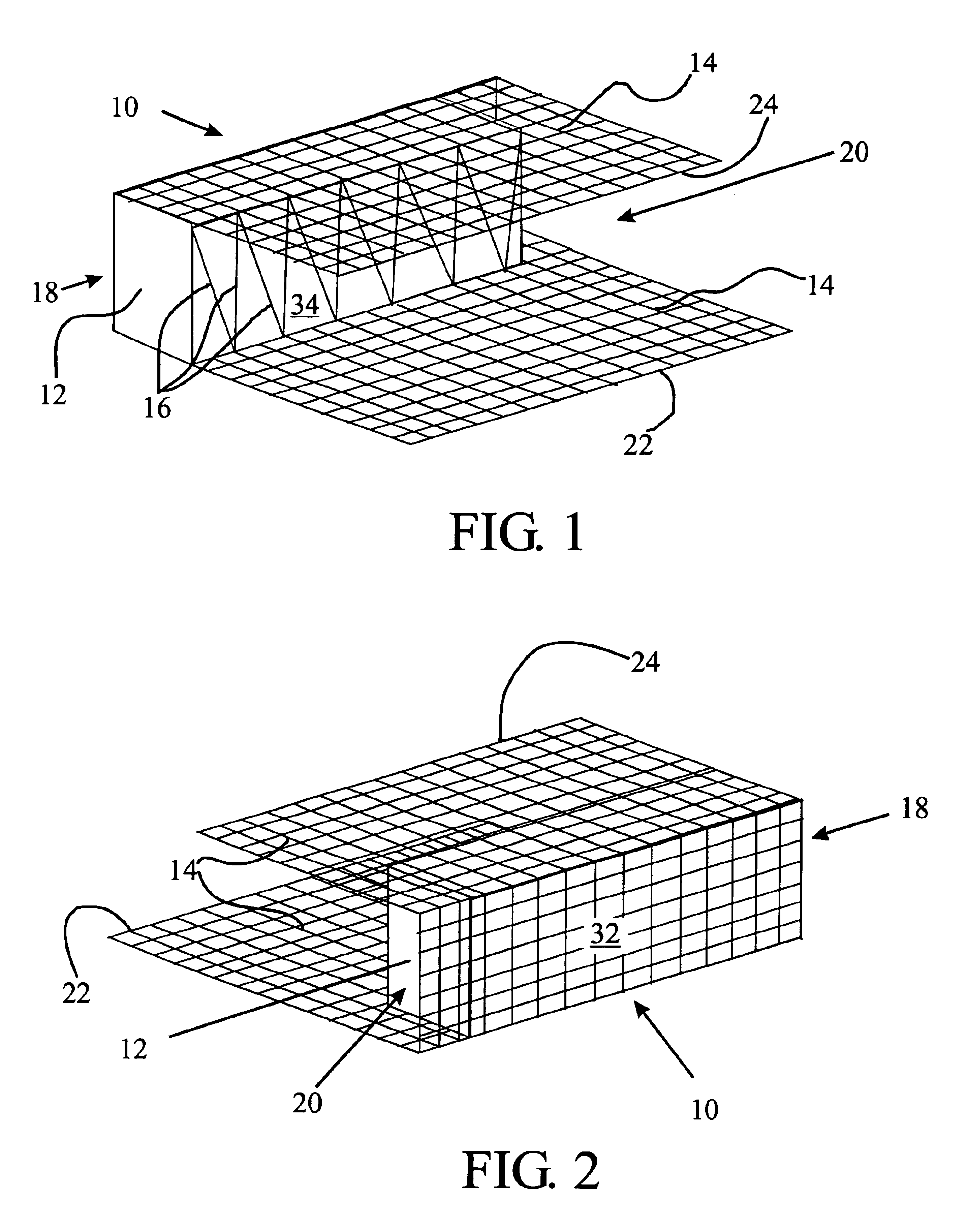
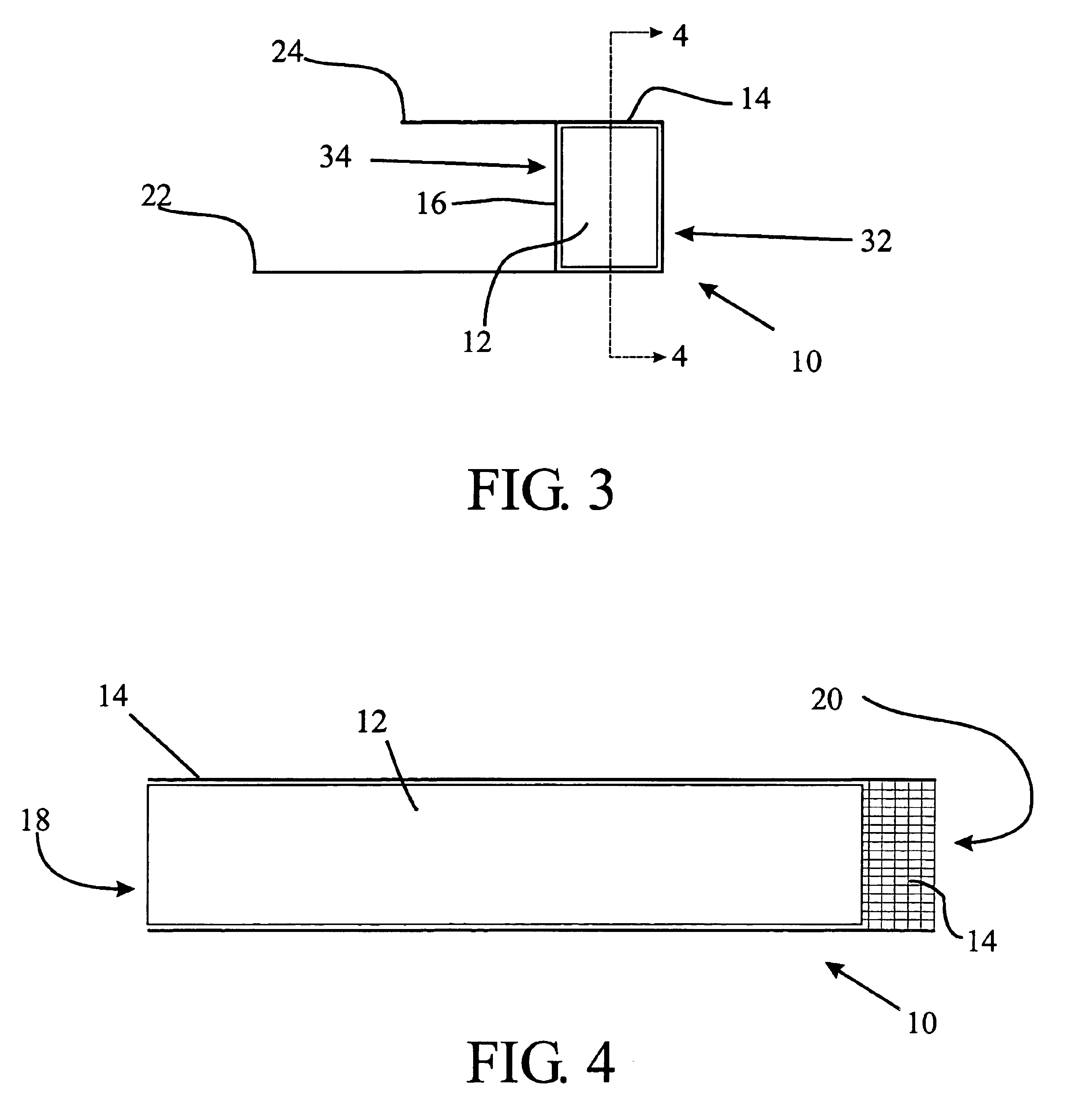
[0037]FIGS. 1-11 illustrate a first embodiment of a fiber block segment 10 of the self-anchoring fiber block system of the invention. As shown in FIGS. 1 and 2, fiber block segment 10 includes a compressed coir fiber block 12 and a high strength coir fabric 14 wrapped around three sides of the compressed coir fiber block 12. The coir fiber block 12 may also be wrapped wi...


PUM


Abstract

A fiber block segment suitable for controlling erosion and stabilizing soil is described that comprises an elongated fiber block formed of a densely packed elongated thick fibrous material. The fiber block is wrapped with a fabric around three sides so that the fabric defines a top anchor portion and a bottom anchor portions extending from the block. The fiber block is securely attached to the wrapped fabric by another fabric or twine spanning the fourth side of the block. Additionally, the fabric is wrapped only up to the edges defining one end (a male end) and beyond the edges defining the opposite end (the female end) to define a pouch-like structure at the female end. The fiber block is made of coconut fibers (coir). The fabric is woven from coir twine, and coir twine secures the fabric to the fiber block.

Description

I. CROSS REFERENCE TO RELATED APPLICATIONS[0001]This application claims priority to U.S. Provisional Patent Application Ser. No. 60 / 354,072 entitled “Self-anchoring fiber block system for shoreline and waterway bank restoration” filed Jan. 30, 2002.II. BACKGROUND OF THE INVENTION[0002]The invention relates to a self-anchoring fiber block system for lining lake or ocean shorelines or the banks of streams or rivers to control erosion of the soil near the water's edge and to promote growth of environmentally friendly vegetation near the waterline. Urban development has led to construction of more and more impervious solid surfaces such as parking lots and paved roads among other man-made structures that impede the natural watershed's ability to absorb and filter rainwater carrying silt from soil erosion and other pollutants before it runs off into streams and other waterways. This unfiltered runoff harms the environment by increasing pollution levels in the waterways within the watersh...

Claims


Application Information

Patent Timeline
Patent Type & Authority Patents(United States)
IPC IPC(8): E02B3/12
CPCE02B3/12E02D17/20E02B3/125Y02A10/11
Inventor SANTHA, B. LANKA
Owner SANTHA B LANKA
Why Eureka
Try Eureka