
Radio frequency resonator and method for producing the same

a radio frequency resonator and resonator inner surface technology, applied in the direction of resonators, accelerators, electric discharge tubes, etc., can solve the problems of radio frequency current flowing on the inner surface of the resonator, deterioration in appearance, and inability to maintain the plating thickness with enough uniformity and reproducibility, etc., to achieve the effect of increasing the electrical conductivity, and reducing the thickness of the plating

Inactive Publication Date: 2005-05-17
SENCORP
View PDF14 Cites 2 Cited by
  • Summary
  • Abstract
  • Description
  • Claims
  • Application Information

AI Technical Summary

Benefits of technology

[0013]This invention intends to solve the abovementioned problems involved in the conventional resonator containers and their production; by aiming at saving processing time (man-hour) in the fabrication of containers and their surface treatment, improving the thermal conductivity, and decreasing the individual differences in the radio frequency loss of containers.
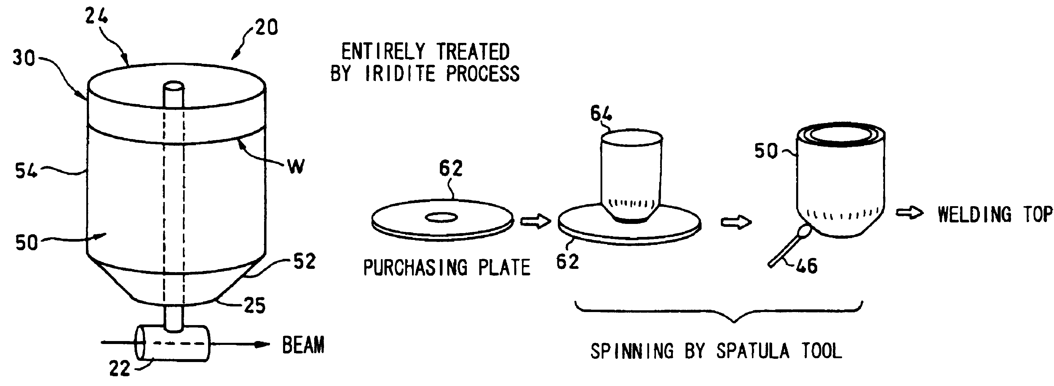
[0030]In the invention, forming the aluminum based material (in particular, a pure aluminum) integrally in one body ensures both sufficient electrical and thermal conductivity, and necessary mechanical strength as well. The application of the Irridite process, when needed, provides corrosion protection and increased electrical conductivity.
[0031]According to the invention, the usage of the aluminum based material and the formation of the corrosion-proof protective coating, when needed, can ensure smaller dispersion of the radio frequency loss in resonator canisters, and save processing time (man-hour) needed for their surface treatments.
[0032]When the pure aluminum is used in particular, the usage thereof can also contribute to the increase in the thermal conductivity of the resonator canister.
[0033]Furthermore, integral forming combined with the usage of the aluminum based material can save the processing time (man-hour) needed for resonator container production.

Problems solved by technology

The reasons why only the inner, but not outer, surface has metallic coating is that the outer surface, if copper or silver plated, would easily be oxidized or discolored when touched with hand, which eventually would result in the deterioration in appearance.
However, the radio frequency current, flowing on the resonator inner surface, is limited within a depth, the skin depth, which depends on the frequency from the skin effect.
However, it is practically impossible to keep the plating thickness with enough uniformity and reproducibility, over the entire resonator inner surface with complicated shape.
Furthermore, plating thickness is very difficult to be inspected in quality control.
Consequently, the plating thickness is liable to differ by each individual container, which eventually causes individual differences in the radio frequency loss among resonator containers.
Due to the difficulty in thickness control, the performance of resonators eventually depends on the uncontrollable plating thickness, which has been a fundamental drawback so far.
In addition, the hardness of aluminum alloy like A6061-T6 used in a resonator container cannot allow the dished head and wall to be formed integrally in one body, and the low thermal conductivity of the alloy causes surface temperature rise, to invite, eventually, unfavorable increase in electrical resistance.
Furthermore, there have been problems of high production cost because the production of resonator containers comprises welding of many components and metal plating with masking, both of which need a lot of manual labor, resulting in much processing time (man-hour).

Method used


Image

  • Radio frequency resonator and method for producing the same
  • Radio frequency resonator and method for producing the same
  • Radio frequency resonator and method for producing the same

Examples


examples

[0051]Expressing the electrical conductivity in terms of “International Annealed Copper Standard (IACS) Conductivity,” wherein the standard annealed copper is assumed to have 100% IACS conductivity, the conductivity of the radio frequency resonator is 43% of the conventional aluminum alloy A6061-T6, but 61%, of the pure aluminum A1050-0 used in the invention. The container of the invention has been proved to have higher electrical conductivity.

[0052]The thermal conductivity has also proved to be higher according to the invention: 0.17 kW / m° C. for the aluminum alloy A6061-T6 used in the conventional resonator, while 0.23 kW / m° C. for the pure aluminum A1050-0 in the invention.

[0053]Regarding the mechanical strength, the container of the invention is strengthened by the work hardening during spinning, but is not so strong as the conventional one made of aluminum alloy. However, by increasing wall thickness to, for example, 3.1 mm or larger for the single-layered cylinder 28 and 3.5 m...


PUM

PropertyMeasurementUnit
thicknessaaaaaaaaaa
thicknessaaaaaaaaaa
thicknessaaaaaaaaaa

Abstract

A dished head and a wall part are integrally formed in one body by spinning, using a flat aluminum based material, and then a corrosion-proof protective coating is formed on the whole surface by the Irridite process to complete the canister. The combination of appropriate material selection and production process saves the processing time (man-hour) needed for forming resonator canisters and its surface treatment, improves the thermal conductivity, and consequently decreases individual differences of the radio frequency loss in resonator canisters.

Description

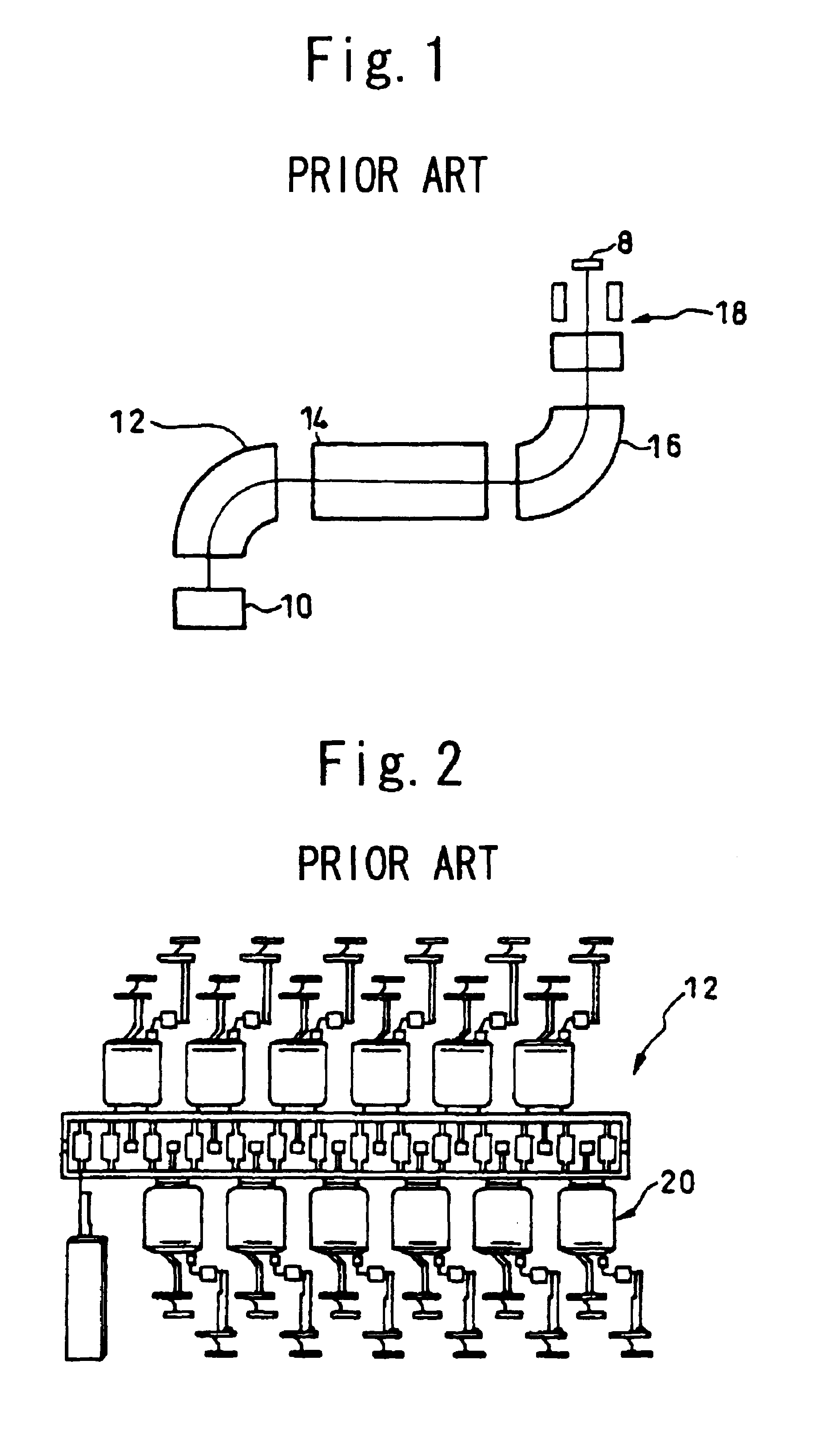
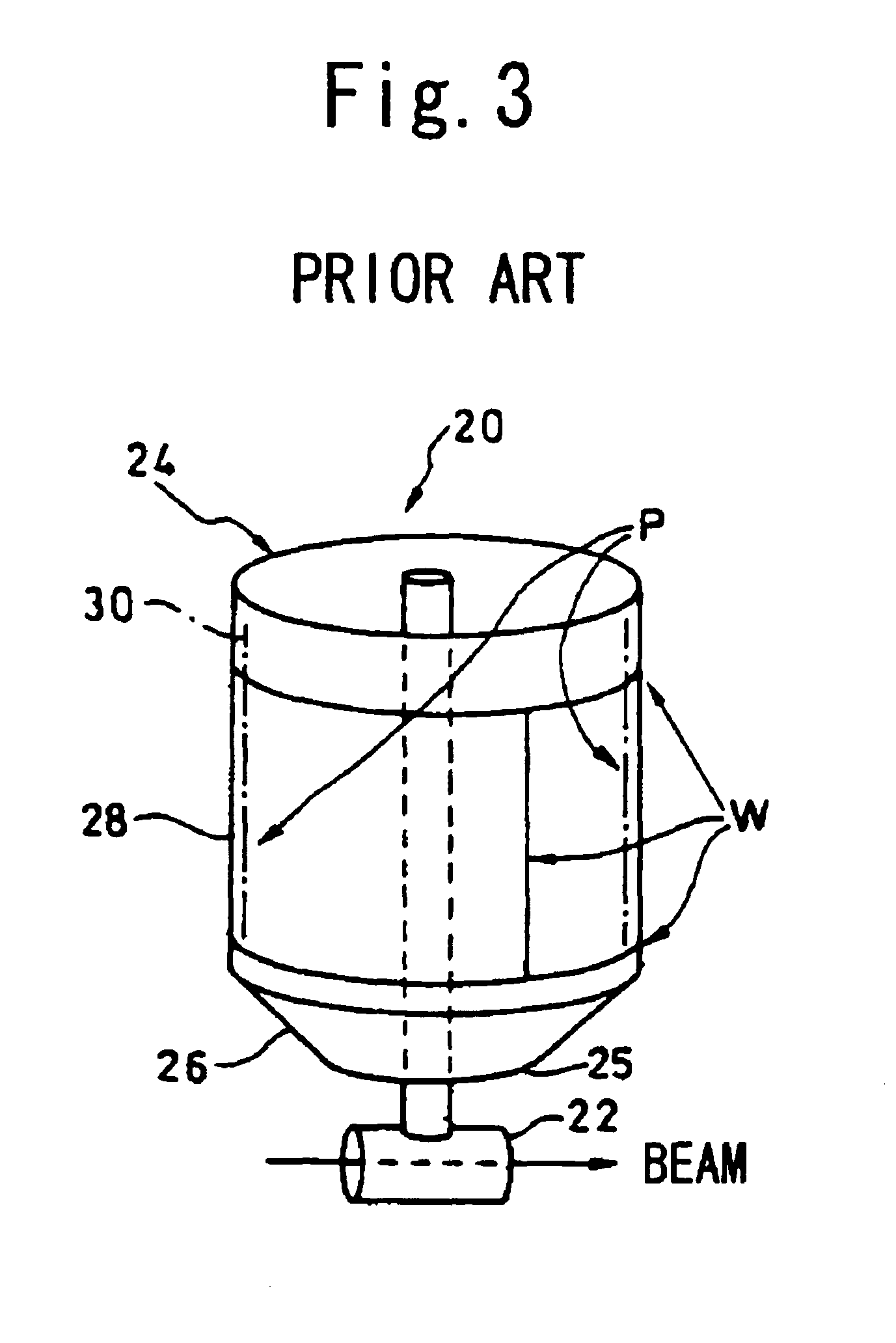
BACKGROUND OF THE INVENTION[0001]1. Field of the Invention[0002]This invention relates to a radio frequency resonator and a method for producing the same, and more specifically, to a radio frequency resonator made of aluminum, which is used in accelerators, beam irradiation apparatuses, and ion implantation apparatuses etc. and to a method for producing the same.[0003]2. Description of the Prior Art[0004]Radio frequency resonators made of aluminum are used as main units in accelerators, beam irradiation apparatuses, ion implantation apparatuses, etc. An example of an ion implantation machine used for implanting ions into silicon wafers 8 is shown in FIG. 1, and has a linear accelerator 14 employing a number of the aluminum radio frequency resonators 20 as shown in FIG. 2. In the drawings, the numeral 10 denotes an ion source, 12 and 16, analyzer magnets, and 18, a scanning unit.[0005]As shown in FIG. 3 in detail, a container 24 of the radio frequency resonator 20 mainly comprises: a...

Claims


Application Information

Patent Timeline
Patent Type & Authority Patents(United States)
IPC IPC(8): H01P11/00H01P7/00H01P7/06H05H9/00H01J37/30H01J37/317H05H7/18
CPCH01J37/32247H01P11/008H01P7/06
Inventor MURAKAMI, YOSHINOBUOHNO, SHIGERU
Owner SENCORP
Learn More