Flat heat pipe provided with means to enhance heat transfer thereof

a technology of heat pipe and heat transfer, which is applied in the direction of insulated conductors, cables, semiconductor/solid-state device details, etc., can solve the problems of wick structure, affecting reliability and longevity of highly-sophisticated electronic devices, and mass generation of heat in the course of their operation, so as to minimize obstruction, improve heat dispersion effect, and reduce the effect of wick structur

Active Publication Date: 2005-06-07
IND TECH RES INST
View PDF13 Cites 100 Cited by
  • Summary
  • Abstract
  • Description
  • Claims
  • Application Information

AI Technical Summary

Benefits of technology

[0009]Each of the heat conduction pillars of the present invention is reinforced by a wick structure which is used to promote a cyclic process of evaporation and condensation of the liquid. The liquid evaporation process brings about an excellent heat di

Problems solved by technology

These electronic components are highly efficient and capable of high performance, thereby resulting in massive generation of heat in the course of their operation.
Such a locally over-heating phenomenon is detrimental to reliability and longevity of a highly-sophisticated electronic device, such as notebook computer.
However, the wick structure is also an obstacle to heat transfer due to its low thermal conductivity.
In another words, the liquid which is attracted to the wick structure would fail to vaporize as expected, thereby resulting in a poor heat dissipation or heat distribution.
In spite of

Method used


Image

  • Flat heat pipe provided with means to enhance heat transfer thereof
  • Flat heat pipe provided with means to enhance heat transfer thereof
  • Flat heat pipe provided with means to enhance heat transfer thereof

Examples


Embodiment Construction

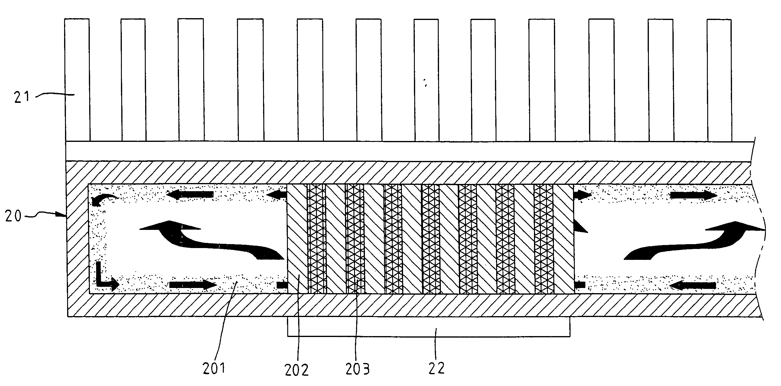
[0019]As shown in FIGS. 5 and 6, a flat heat pipe embodied in the present invention is provided with a vacuum chamber 20 which is made of a material having an excellent heat conduction property, such as copper, aluminium, and the like. A cooling device 21 is mounted on the vacuum chamber 20 which is connected at an underside thereof with a heating element 22.

[0020]The vacuum chamber 20 is provided in the surface of an interior thereof with a wick structure 201. An appropriate amount of a working fluid, such as pure water, ammonia, organic solution like methanol, ethanol or acetone, is contained in the chamber 20. The working fluid serves to disperse heat by evaporation and may contain metallic or nonmetallic powder in various ratios as desired. The working fluid is confined to the wick structure 201 by virtue of capillarity. As the working fluid comes in contact with the heat source, the working fluid is caused to evaporate such that the vapor rises to a cooler position, so as to fo...


PUM


Abstract

A flat heat pipe has a vacuum chamber, an evaporator connected to a heating element, and a condenser connected to a cooling device. The vacuum chamber is provided in an interior with a wick structure and a working fluid by which an evaporation-condensation cyclic process is effected. The vacuum chamber is further provided in the interior with a plurality of heat conduction pillars, which are confined to the area of the evaporator and are connected with an upper wall and a lower wall of the interior of the chamber. The heat conduction pillars serve to enhance the heat conduction to the condenser from the evaporator.

Description

FIELD OF THE INVENTION[0001]The present invention relates generally to a flat heat pipe, and more particularly to a structure for enhancing heat transfer of the flat heat pipe. The structure comprises a plurality of heat conduction pillars, which are located in a hot spot area of a chamber of the flat heat pipe in such a way that the heat conduction pillars are extended between an upper wall and a lower wall of the hot spot area of the chamber. The heat conduction pillars serve to attain heat dissipation and uniform temperature distribution of the flat heat pipe.BACKGROUND OF THE INVENTION[0002]The state-of-the-art electronic device comprises a number of the miniaturized electronic components per unit volume. These electronic components are highly efficient and capable of high performance, thereby resulting in massive generation of heat in the course of their operation. In light of design variation of the electronic components, the heat flux distribution on the surface of the electr...

Claims


Application Information

Patent Timeline
IPC IPC(8): F28D15/04
CPCF28D15/046
Inventor JIN-CHERNG, SHYUCHE-WEI, LINLAN-KAI, YEHMING-JYE, TSAISHAO-WEN, CHENCHENG-TAI, CHUNG
Owner IND TECH RES INST
Why Eureka
Try Eureka