

Membrane module for gas transfer and membrane supported biofilm process
- Summary
- Abstract
- Description
- Claims
- Application Information
AI Technical Summary
Benefits of technology
Problems solved by technology
Method used
Image

Examples
first embodiment
A First Embodiment
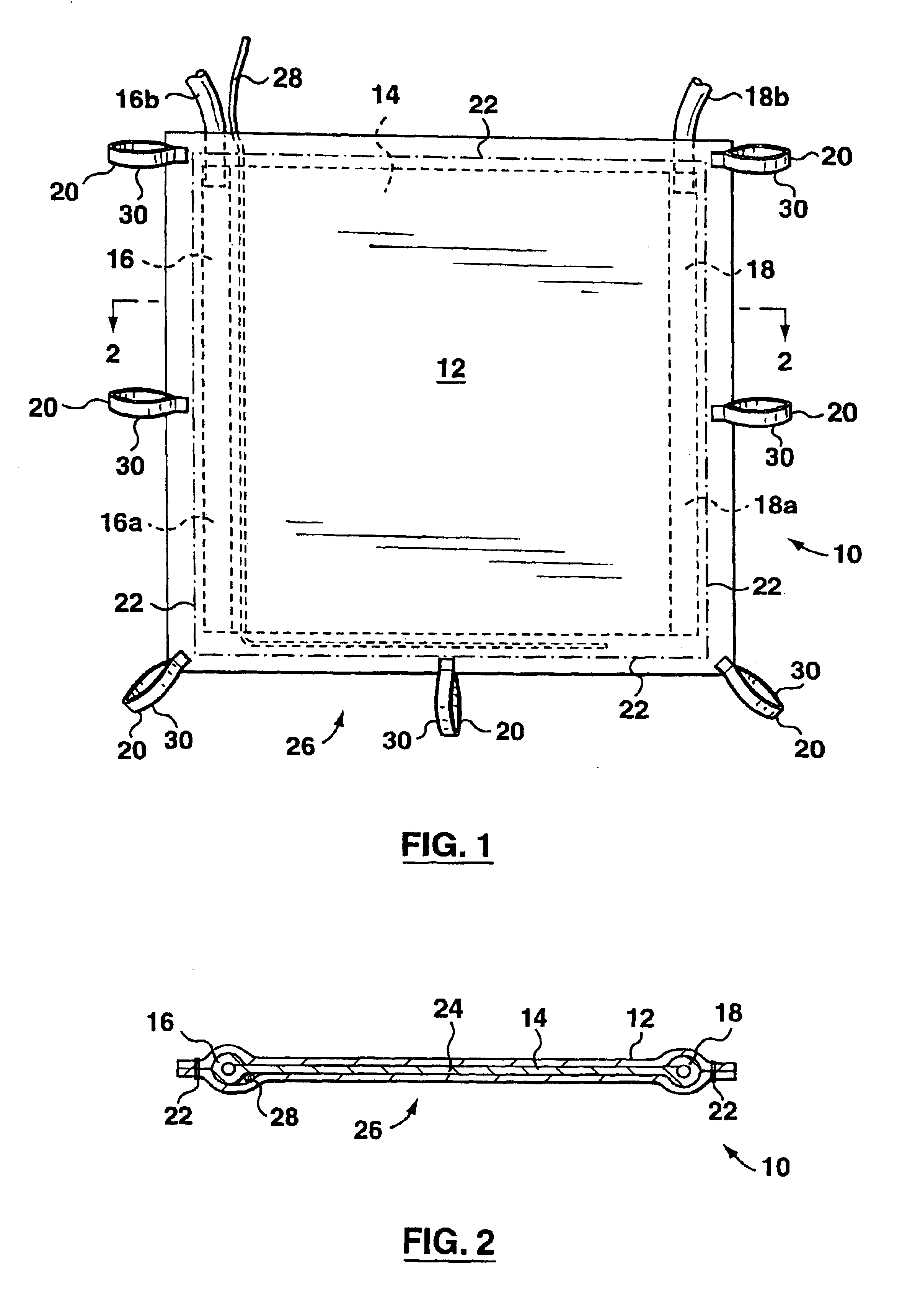
[0039]FIGS. 1 and 2 show a first apparatus 10 having a membrane 12, a spacer 14, an inlet conduit 16, an outlet conduit 18, and a non-rigid restraint system 20.
[0040]The membrane 12 is a sheet material that can be sewed or glued into a variety of constructions. In the embodiment illustrated, a piece of the sheet material of an appropriate size, which may be made of several smaller pieces, is folded in half around the spacer 14 and fastened to itself with a line of stitching 22 or glue. All lines of stitching 22 of the first apparatus 10 (and all subsequent apparatuses described below) expected to be in contact with water are sealed by coating them with liquid silicone rubber or another waterproof adhesive. The membrane 12 thus encloses an inner space 24 containing the spacer 14. The spacer 14 and the membrane 12 together form a planar element 26.
[0041]The membrane 12 is flexible and gas diffusive but liquid water impermeable. By liquid water impermeable, we mean th...
second embodiment
A Second Embodiment
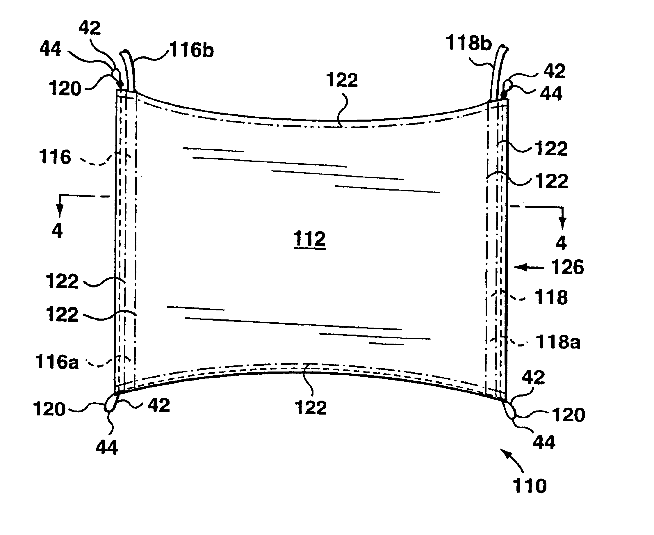
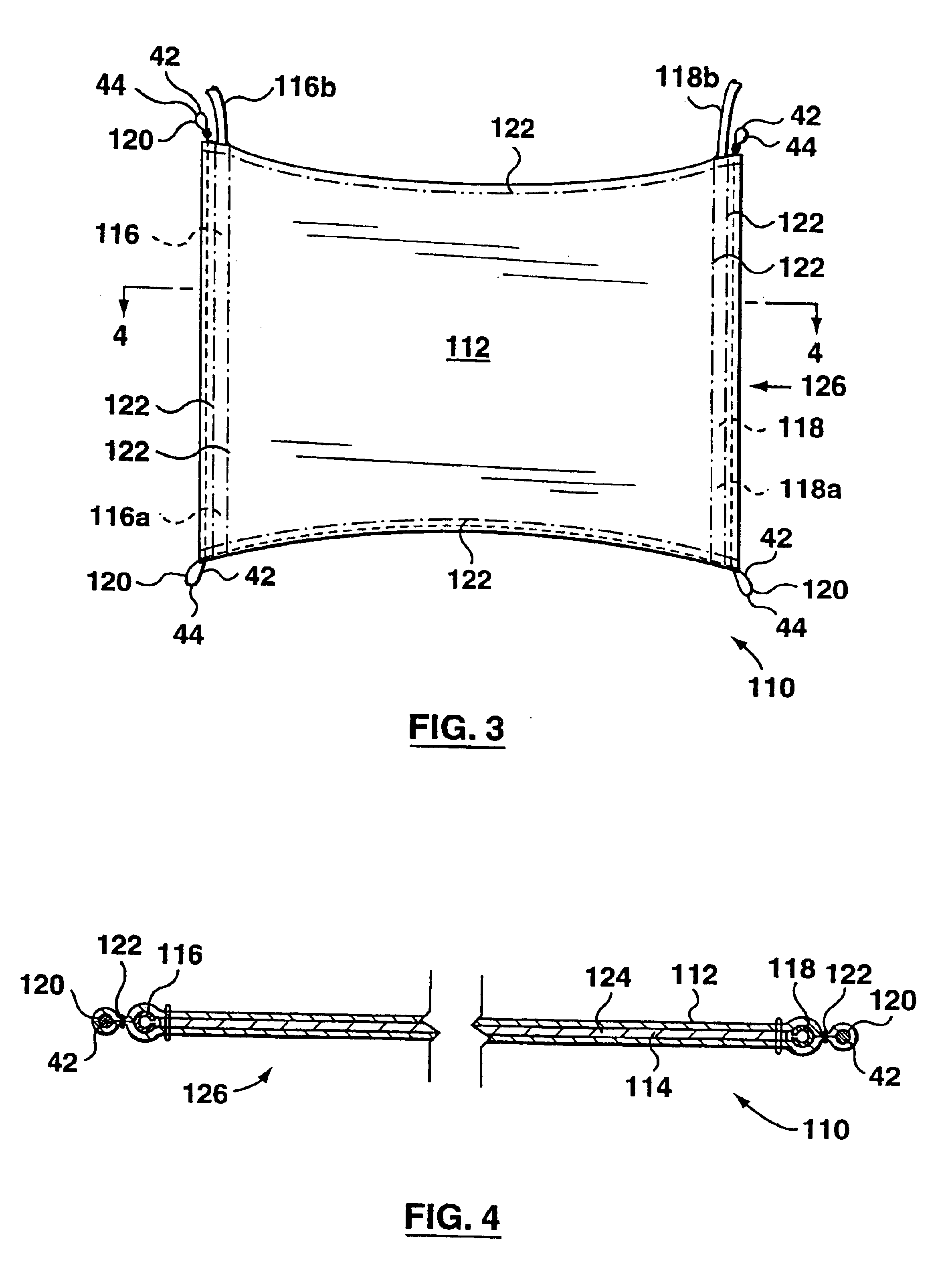
[0049]FIGS. 3, 4 and 5 show a second apparatus 110 for supporting and oxygenating an immersed biofilm. The second apparatus 110 has a membrane 112, a spacer 114, an inlet conduit 116, an outlet conduit 118, and a non-rigid restraint system 120.
[0050]The membrane 112 and spacer 114 are of the same material described for the first embodiment. The membrane 112 is similarly folded around the spacer 114 and fastened to itself with a line of stitching 122 or glue. Additional lines of stitching 122 are used to fix the inlet conduit 116, outlet conduit 118 and second restraint system 120 in the positions shown. The membrane 112 thus encloses an inner space 124 containing the spacer 114 and the spacer 114 and the membrane 112 together form a planar element 126.
[0051]The inlet conduit 116 and the outlet conduit 118 have first ends 116a and 118a in fluid communication with the inner space 124. The inlet conduit 116 and the outlet conduit 118 each also have second ends 116b a...
third embodiment
A Third Embodiment
[0054]FIGS. 6 and 7 show a third apparatus 210. The third apparatus 210 has a membrane 212, a spacer 214, an inlet conduit 216, an outlet conduit 218, and a non-rigid restraint system 220.
[0055]The membrane 212 is a sheet material as described for the previous embodiments. The structure of the third apparatus differs, however, in that the membrane 212 is folded around two layers of spacer 214 separated by a flexible but impermeable separator 50, preferably a plastic sheet. The edges of the membrane are fastened together by waterproof glue or a line of stitching 222 made waterproof with silicone rubber spray or glue. The membrane 212 thus encloses an inner space 224 containing the spacer 214 and the spacer 214 and the membrane 212 together form a planar element 226.
[0056]The inlet conduit 216 and the outlet conduit 218 have first ends 216a, 218a in fluid communication with the inner space 224. The inlet conduit 216 and the outlet conduit 218 also have second ends 21...
PUM
| Property | Measurement | Unit |
|---|---|---|
| Length | aaaaa | aaaaa |
| Flexibility | aaaaa | aaaaa |
| Gas permeability | aaaaa | aaaaa |
Abstract
Description
Claims
Application Information