Control of chemical mechanical polishing pad conditioner directional velocity to improve pad life

a technology of polishing pad conditioner and directional velocity, which is applied in the direction of total factory control, abrasive surface conditioning devices, lapping machines, etc., can solve the problems of premature wear, excessive polishing pad conditioning, and loss of roughness and elasticity of polishing pads, so as to prolong increase the number of semiconductor wafers. , the effect of prolonging the working life of pads

Inactive Publication Date: 2005-06-28
APPLIED MATERIALS INC
View PDF408 Cites 57 Cited by
  • Summary
  • Abstract
  • Description
  • Claims
  • Application Information

AI Technical Summary

Benefits of technology

[0010]The present invention relates to a method, system and medium for conditioning a planarizing surface of a polishing pad in order to extend the working life of the pad. More specifically, at least some embodiments of the present invention use physical and/or chemical models (which can be implemented as a single model or multiple models) of the pad wear and w

Problems solved by technology

Over time the polishing pad loses its roughness and elasticity, and thus, its ability to maintain desired removal rates (polishing rates).
Furthermore, excessive pad conditioning shortens pad life.
A problem with conventional conditioning methods is that they may over-condition, e

Method used


Image

  • Control of chemical mechanical polishing pad conditioner directional velocity to improve pad life
  • Control of chemical mechanical polishing pad conditioner directional velocity to improve pad life
  • Control of chemical mechanical polishing pad conditioner directional velocity to improve pad life

Examples


Embodiment Construction

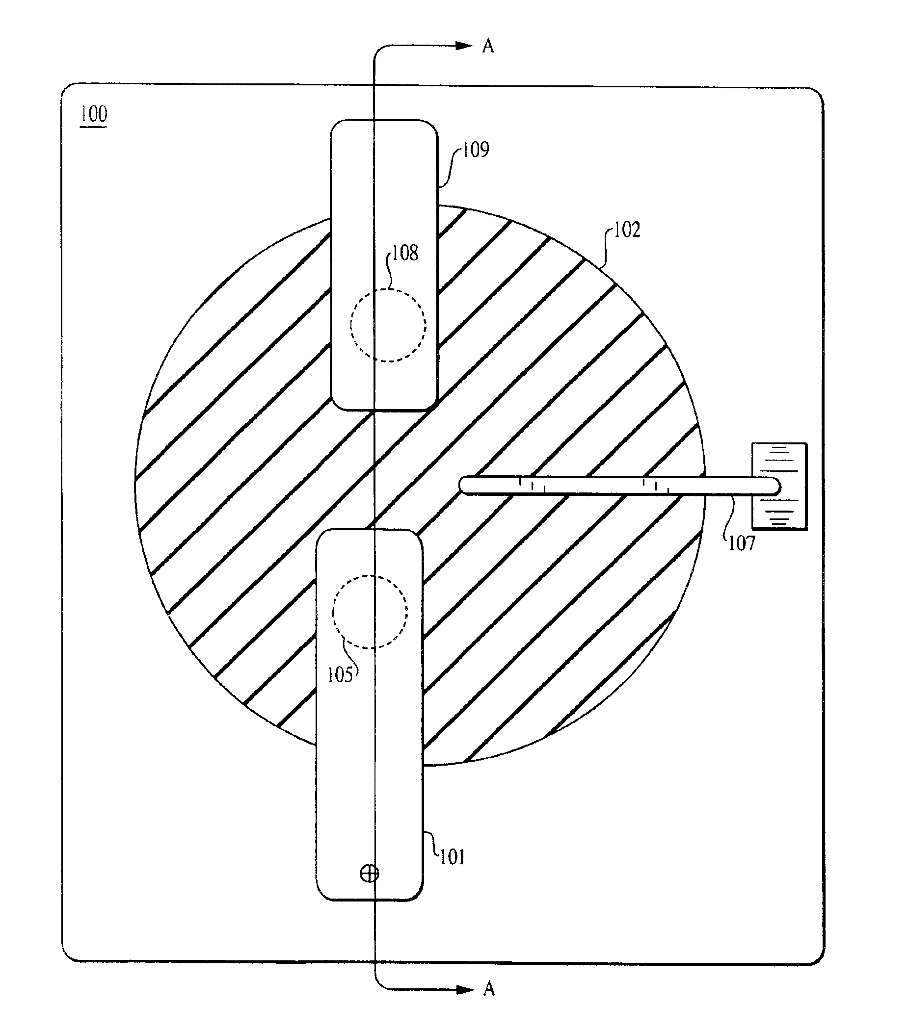
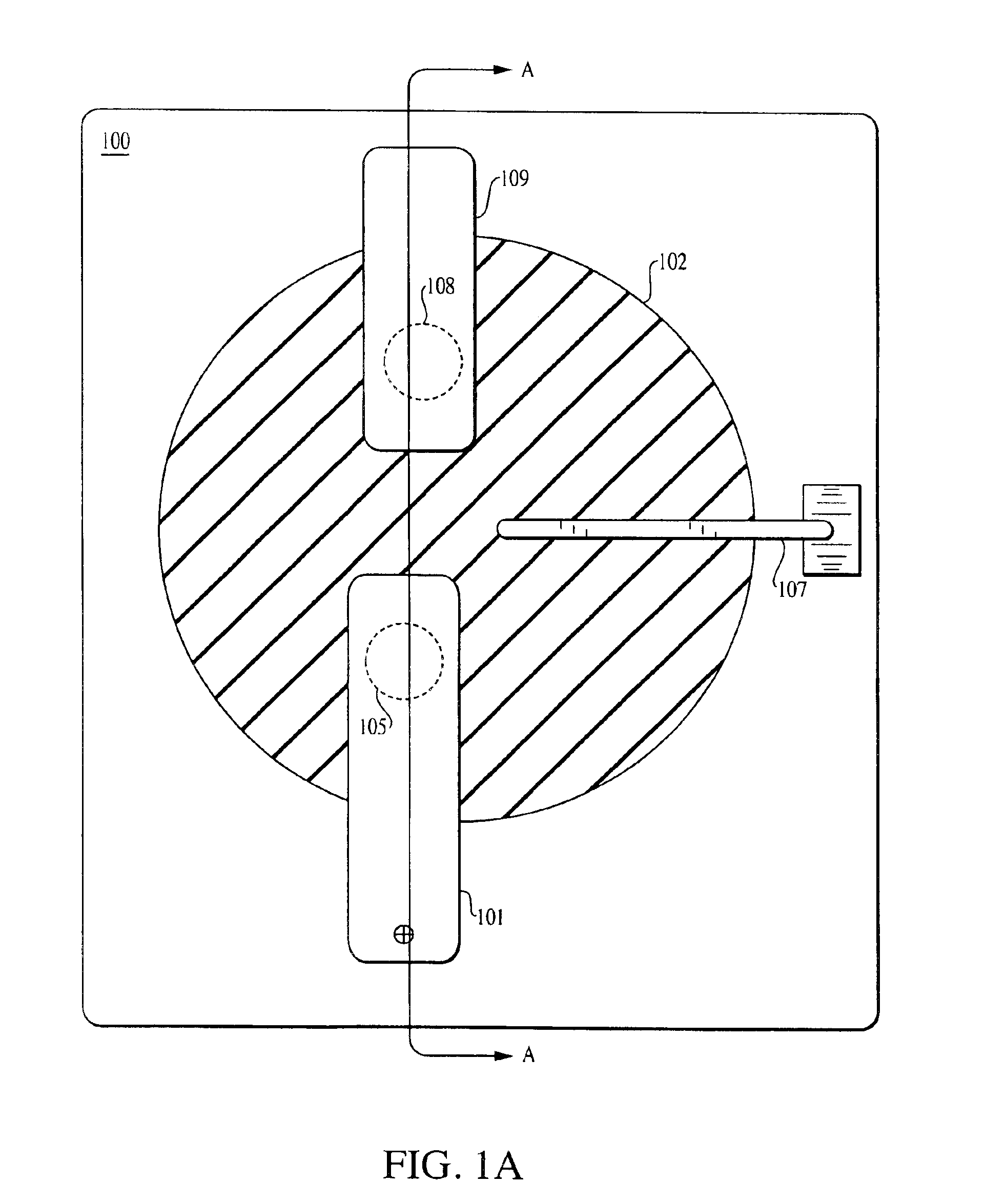
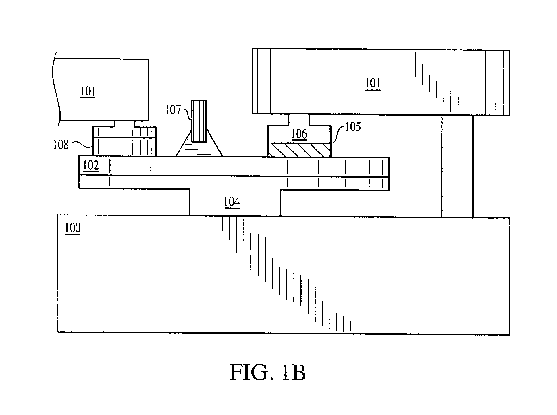
[0071]Novel methods for feed forward and feed back controls of the CMP process for maximizing the life of the polishing pad are described herein. Extended pad life results in reduced down time for the CMP process because the polishing pad can polish more wafers over a longer period of time without requiring replacement or adjustment (e.g., removal of the damaged portion of the pad). The term wafer is used in a general sense to include any substantially planar object that is subject to polishing. Wafers include, in additional to monolith structures, substrates having one or more layers or thin films or other architecture deposited thereon.

[0072]The polishing pad surface needs to maintain a certain level of roughness and elasticity in order to provide the required wafer material removal rates in a CMP process. The roughness and elasticity of the pad decreases with successive wafer polishes, thereby reducing the wafer material removal rate. Initial polishing pad surface conditions (asp...


PUM

PropertyMeasurementUnit
Timeaaaaaaaaaa
Speedaaaaaaaaaa
Frequencyaaaaaaaaaa

Abstract

A method, apparatus and medium of conditioning a planarizing surface includes installing a wafer to be polished in a chemical mechanical polishing (CMP) apparatus having a polishing pad and a conditioning disk, polishing the wafer under a first set of pad conditioning parameters selected to maintain wafer material removal rates with preselected minimum and maximum removal rates, determining a wafer material removal rate occurring during the polishing step, calculating updated pad conditioning parameters to maintain wafer material removal rates within the maximum and minimum removal rates, and conditioning the polishing pad using the updated pad conditioning parameters, wherein the updated pad conditioning parameters are calculated by a pad wear and conditioning model that predicts the wafer material removal rate of the polishing pad based upon the rotational speed and direction of the conditioning disk.

Description

RELATED APPLICATIONS[0001]This application claims priority under 35 U.S.C. §119(e) from now abandoned application Ser. No. 60 / 298,878 filed Jun. 19, 2001 and entitled “Advanced Process Control for Semiconductor Manufacturing Process.”[0002]This application claims priority under 35 U.S.C. §119(e) from now abandoned application Ser. No. 60 / 305,798, filed Jul. 16, 2001 and entitled “Feedforward and Feedback Control for Conditioning of Chemical Mechanical Polishing Pad.”[0003]This application claims priority under 35 U.S.C. §119(e) from now abandoned application Ser. No. 60 / 318,743, filed Sep. 12, 2001 and entitled “Feedforward and Feedback Control for Conditioning of Chemical Mechanical Polishing Pad.”FIELD OF THE INVENTION[0004]The present invention is generally directed to the area of polishing and methods for improving the life and effectiveness of polishing pads in a chemical mechanical polishing process.BACKGROUND OF THE INVENTION[0005]Chemical-mechanical polishing (CMP) is used i...

Claims


Application Information

Patent Timeline
IPC IPC(8): B24B49/03B24B49/02B24B49/00B24B49/18B24B37/04B24B53/007G05B19/19G05B19/00G05B19/418H01L21/00H01L21/66H01L21/02H01L21/3105B24B53/017B24B37/005H01L21/304
CPCB24B37/013H01L22/20B24B49/03B24B49/18B24B53/017G05B19/00G05B19/19G05B19/41865H01L21/67253H01L21/67276B24B37/042G05B2219/32053G05B2219/32065G05B2219/45031H01L21/31053Y02P80/40Y02P90/02B24B37/005B24B37/04H01L21/304
Inventor PAIK, YOUNG JOSEPH
Owner APPLIED MATERIALS INC
Why Eureka
Try Eureka