

Device and signal processing circuit for magnetic recording, magnetic recording apparatus
a signal processing circuit and recording device technology, applied in the field of magnetic recording/reproducing apparatus, can solve the problems of increasing data error rate, unable to remove dc components, etc., and achieve the effect of reducing the signal-to-noise ratio, and reducing the error rate of detection data
- Summary
- Abstract
- Description
- Claims
- Application Information
AI Technical Summary
Benefits of technology
Problems solved by technology
Method used
Image

Examples
embodiment 1
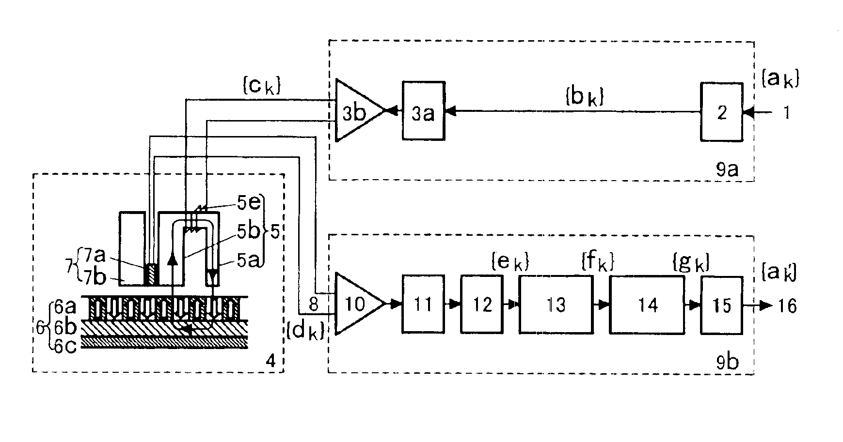
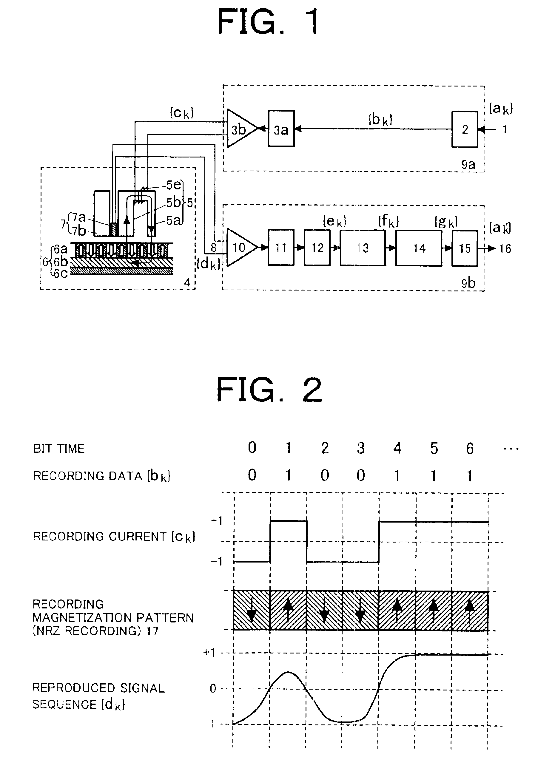
[0022]FIG. 1 shows the fundamental configuration of an embodiment of a magnetic recording / reproducing apparatus according to the present invention. In this embodiment, information code data 1 {ak} (in which k is an integer indicating a bit-interval) supplied to a recording signal processing circuit 9a is subjected to a predetermined code conversion process in an encoder 2 for adding a run-length limitation and an error correction code, so that the data is converted into recording code data {bk}. The recording code data {bk} is converted into an analog recording current signal {ck} via a data-to-recording current conversion circuit 3a and a recording signal amplifier 3b. Thereafter, the signal {ck} is supplied to a perpendicular magnetic recording head medium system 4, recording the information.
[0023]A recording medium 6 used in the perpendicular magnetic recording head medium system 4 is a double-layer film perpendicular magnetic recording medium having both a recording magnetic lay...
embodiment 2
(Embodiment 2)
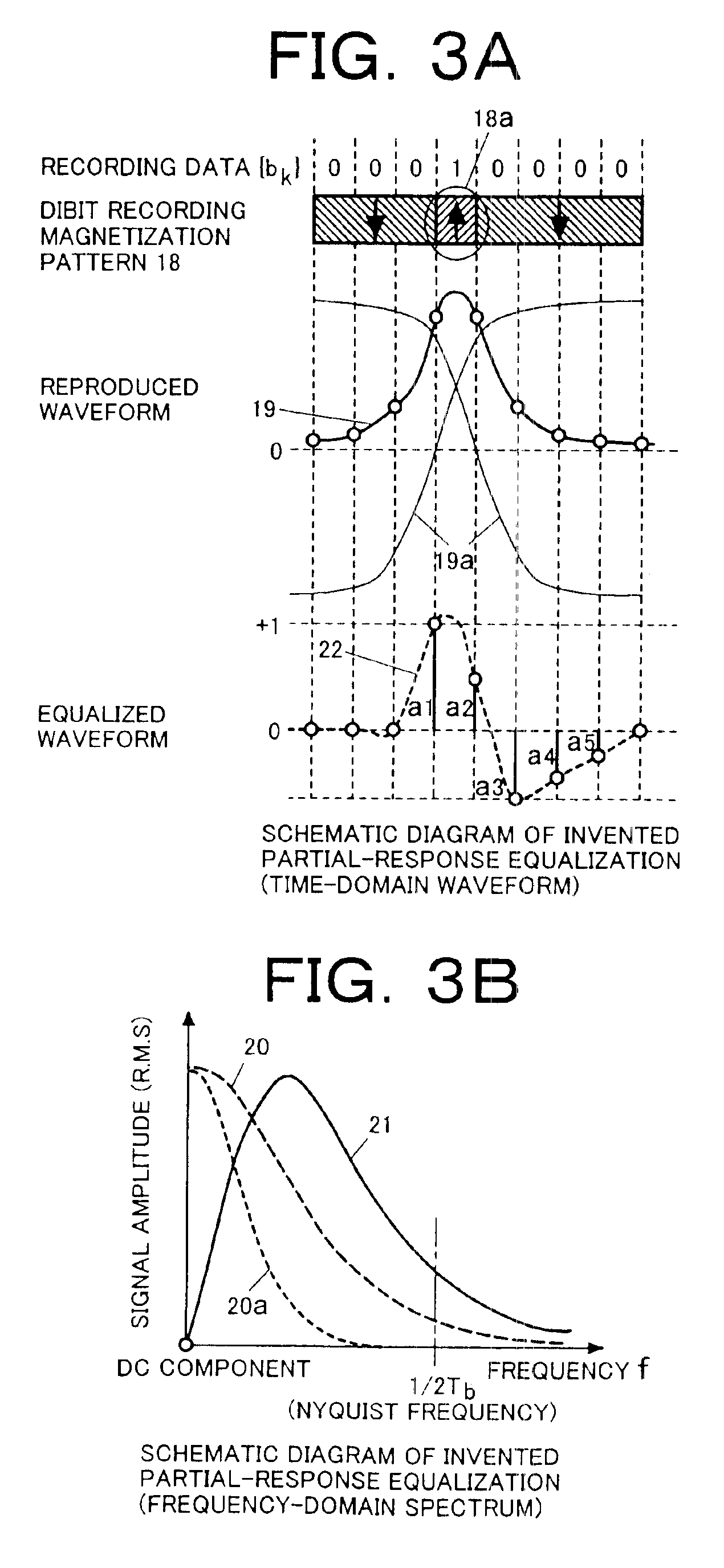
[0034]FIG. 7 shows a second embodiment of the present invention. In this-embodiment, the equalizer 13 is composed of a (1, 0, −1) equalizer 28a, and a (s1, s2, s3, . . . sn) partial-response interference value adding circuit 28b. In the (1, 0, −1) equalizer 28a, the dibit reproduced waveform 19 is shaped into a short-bit waveform having intersymbol interference (1, 0, −1) of a partial-response class 4. Then, in the (s1, s2, s3, . . . sn) partial-response interference value adding circuit 28b, desired values of partial-response interference are added. On this occasion, waveform response of the values of interference (s1, s2, s3−s1, . . . , sk−sk−2, . . . , sn−sn−2, −sn−1, −sn) corresponding to the input of the dibit reproduced waveform 19 is obtained on the whole of the equalizer 13. While the output of the (1, 0, −1) equalizer 28a is monitored, a gain control signal 29c for the reproduced signal 8 may be generated adaptively by use of an automatic gain control circuit ...
PUM
| Property | Measurement | Unit |
|---|---|---|
| DC-null frequency | aaaaa | aaaaa |
| length | aaaaa | aaaaa |
| frequency | aaaaa | aaaaa |
Abstract
Description
Claims
Application Information