Electrochemical device and process for producing same

a technology of electrochemical devices and electrode layers, which is applied in the manufacture of secondary cells, final product manufacturing, and grouping of flat cells, etc., can solve the problems of aluminum foils affecting the adhesion of electrode layers, increasing internal resistance, and deteriorating cycle properties, so as to reduce internal resistance and enhance cycle properties

Inactive Publication Date: 2005-06-28
TDK CORPARATION
View PDF9 Cites 43 Cited by
  • Summary
  • Abstract
  • Description
  • Claims
  • Application Information

AI Technical Summary

Benefits of technology

[0012]Therefore, an object of the invention is to provide electrochemical devices such as electric double layer capacitors and secondary batteries while ensuring adhesivity of a current collector and an electrode layer, enhancing cycle properties and reducing their internal resistances, without requiring a complicated manufacturing process.

Problems solved by technology

In the current collector that uses a metal foil as described above, there is a problem in adhesivity of the metal foil with the electrode layer, which sometimes causes an increase in the internal resistance or detachment of the electrode layer from the current collector, so that cycle properties would be deteriorated when charging and discharging are performed repeatedly.
Especially, current collectors made of aluminum foils noticeably raise the problem of insufficient adhesivity with the electrode layer.
This inevitably leads to a decrease in energy density.
However, in the case in which the electrode and the current collector are bonded by an adhesive resin, there is a problem that the energy density is decreased due to the presence of thickness of the adhesive resin layer, which is necessitated by use of the adhesive resin.
Therefore, it is difficult to provide sufficient adhesivity.
Therefore, in electrochemical devices having such structures, problems such as an increase in the internal resistance and deterioration in the energy density would arise, when an adhesive resin layer is provided in order to ensure adhesivity of an electrode layer and a current collector.

Method used


Image

  • Electrochemical device and process for producing same
  • Electrochemical device and process for producing same

Examples


example 1

(Formation of Adhesive Resin Layer)

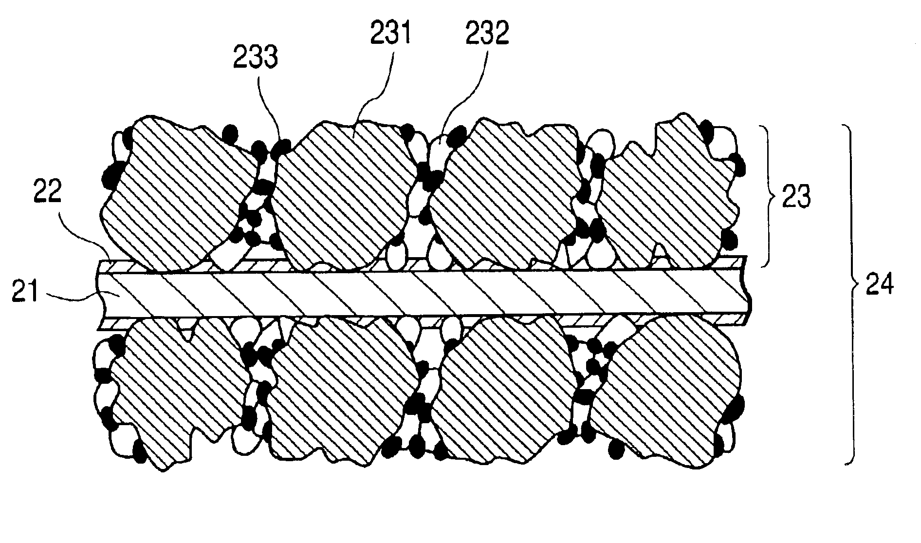
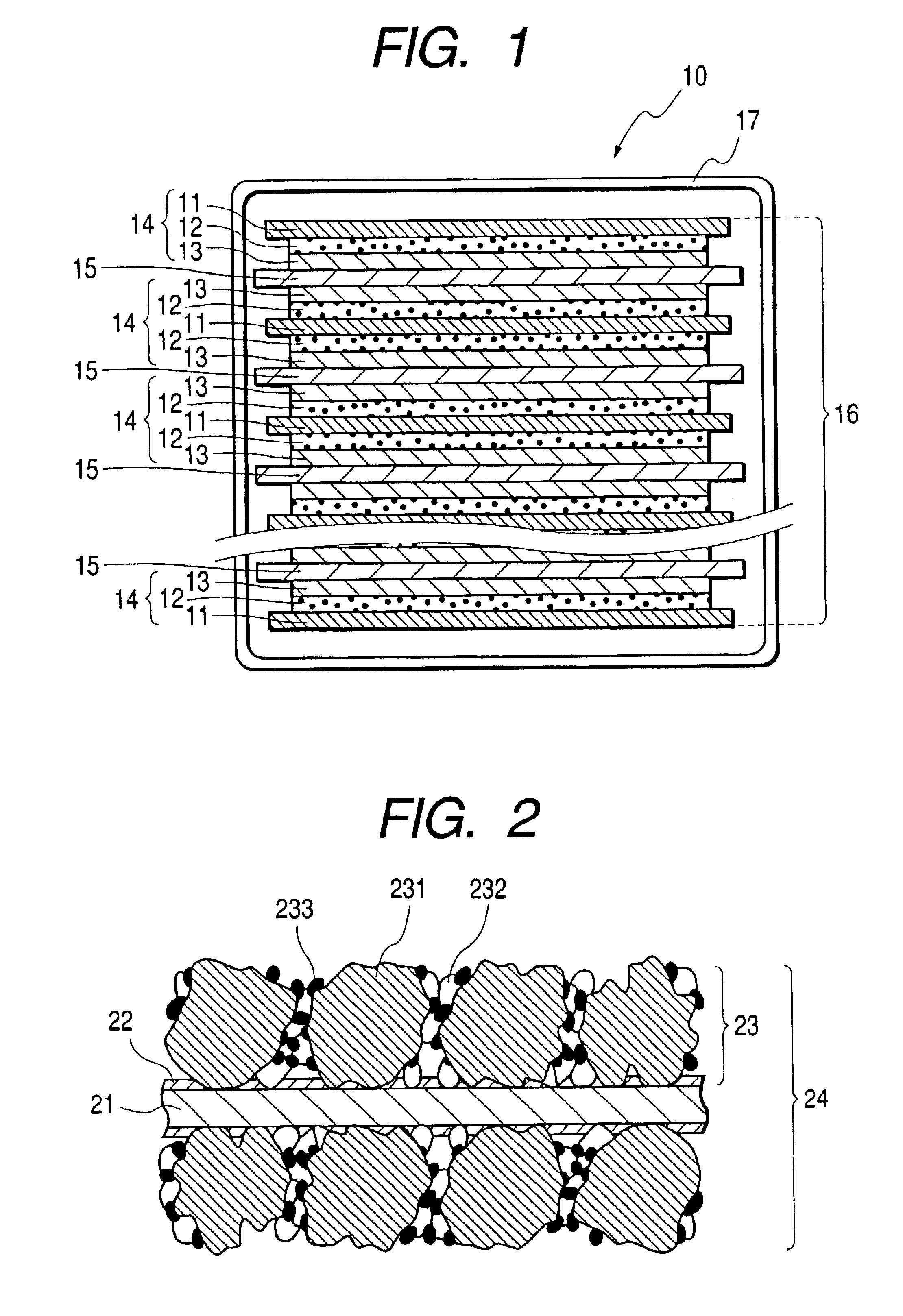
[0065]A resin coating liquid was prepared by having an adhesive resin of a fluorine rubber (Viton-GF manufactured by Dupon) dissolved in a solvent of methyl ethyl ketone (MEK: boiling point=80° C.) with the weight ratio Viton-GF / MEK=5 / 95. The methyl ethyl ketone solvent is a good solvent for the fluorine rubber as the adhesive resin. The resin coating liquid thus made was applied to the whole surface of an aluminum foil having a thickness of 20 μm serving as a current collector, so that an adhesive resin layer was formed. The thickness of the adhesive resin layer after the solvent was evaporated was about 0.08 μm.

(Formation of Electrode)

[0066]As an active material, activated carbon fiber having a specific surface area of about 1000 m2 / g, a diameter of 10 μm and a length of about 30 μm was used. The particle diameter of this active material is 30 μm in accordance with the definition of the particle diameter, since the length is larger than the diame...

example 2

[0078]Example 2 of the electric double layer capacitor was made by a process that is basically the same as the process for making example 1 except that the linear pressure of the calender roll during the rolling was set to 1400 kg·f / cm. The same tests and evaluations as those performed on example 1 were also performed on example 2. The results of the tests are shown in Table 2.

[0079]

TABLE 2Example 2RemarksAdhesive resinAdhesive resin layerFluorinelayerrubberLayer thickness (μm)0.08Rolling conditionLinear pressure of calender roll1400(kg · f / cm)AdhesivityCross-cut adhesion test100 / 100goodevaluation(remaining samples / testedsamples)InternalImpedance (Ω)0.27goodresistanceevaluationCycle propertyElectric capacitance in 1st cycle3.1evaluation(F)Electric capacitance in 100th3.1cycle (F)Ratio of change in electric0goodcapacitance (%)

[0080]As seen from the result of the cross-cut adhesion test shown in Table 2, the adhesivity of the electrode layer and the current collector in example 2 was ...

example 3

[0081]Example 3 of the electric double layer capacitor was made by a process that is basically the same as the process for making example 1 except that the rolling process was omitted. The same tests and evaluations as those performed on example 1 were performed on example 3. The results of the tests are shown in Table 3.

[0082]

TABLE 3Example 3RemarksAdhesive resinAdhesive resin layerFluorinelayerrubberLayer thickness (μm)0.08Rolling conditionLinear pressure of calender roll—(kg · f / cm)AdhesivityCross-cut adhesion test100 / 100goodevaluation(remaining samples / testedsamples)InternalImpedance (Ω)0.56goodresistanceevaluationCycle propertyElectric capacitance in 1st cycle3evaluation(F)Electric capacitance in 100th3cycle (F)Ratio of change in electric0goodcapacitance (%)

[0083]As seen from the result of the cross-cut adhesion test shown in Table 3, the adhesivity of the electrode layer and the current collector in example 3 was good or high, and therefore example 3 had good cycle properties....


PUM

PropertyMeasurementUnit
thicknessaaaaaaaaaa
thicknessaaaaaaaaaa
thicknessaaaaaaaaaa

Abstract

An electrochemical device includes electrodes stacked one on the other with a separator intervening between the adjacent electrodes. The electrode includes a current collector and an electrode layer stacked on the current collector via an adhesive resin layer. The electrode layer contains an active material, an electrically conductive auxiliary and a binder resin. At least part of the electrically conductive auxiliary or the active material penetrates the adhesive resin layer to establish an electrical connection with the current collector.

Description

BACKGROUND OF THE INVENTION[0001]1. Field of the Invention[0002]The present invention relates to an electrochemical device and a process for producing an electrochemical device.[0003]2. Related Background Art[0004]With the development and prevalence of portable electronic instruments, research is increasingly focused on secondary (or rechargeable) batteries such as lithium ion batteries having a high electric capacity capable of continuous operation for a long time and electrochemical devices such as electric double layer capacitors. Such an electrochemical device has a structure composed of electrodes that are stacked one on another with an electrolyte intervening between them. The electrode is composed of a current collector on the surface of which an electrode layer containing an active material is formed. The electrolyte is composed of a separator impregnated with an electrolyte.[0005]In the electric double layer capacitor, a metal foil of aluminum, nickel, copper or stainless s...

Claims


Application Information

Patent Timeline
Patent Type & Authority Patents(United States)
IPC IPC(8): H01G9/00H01G9/016H01G9/008H01G9/058H01M10/18H01M10/00H02J7/00H01M4/02H01G9/155H01M10/36H01M10/06H01M10/40H01G11/10H01G11/22H01G11/24H01G11/28H01G11/38H01G11/40H01G11/66H01G11/86H01M4/13H01M4/139H01M4/62H01M10/04H01M10/05H01M10/0585
CPCH01M4/0404H01M4/0409H01M4/13H01M4/621Y10T29/417H01M10/0413Y02E60/122Y02E60/10Y02P70/50
Inventor TAKAHASHI, TETSUYAKOSUDA, ATSUKOIIJIMA, TADAYOSHI
Owner TDK CORPARATION
Why Eureka
Try Eureka