Light emitting diode module

a technology of led modules and light-emitting diodes, which is applied in the direction of electric variable regulation, process and machine control, instruments, etc., can solve the problems of limited commercialization success of led modules according to these distribution schemes, time-consuming led rearrangement according to a desired distribution, and difficult to achieve the desired distribution

Inactive Publication Date: 2005-07-05
LEATEC FINE CERAMICS
View PDF2 Cites 53 Cited by
  • Summary
  • Abstract
  • Description
  • Claims
  • Application Information

AI Technical Summary

Benefits of technology

[0008]An object of the invention is therefore to provide an LED module with good heat dissipation efficiency, large illumination area and full-area illumination.
[0010]The LED module includes a plurality of epitaxy chips, a plurality of electrode sets, and a substrate with good electrical insulation and heat dissipation. The epitaxy chips, formed by cutting an epitaxy wafer, are mounted on the substrate. The LED module has high heat dissipation efficiency, thereby increasing its performance. The electrodes are arranged in such a manner that the illuminating area of the LED module is not shielded by the electrodes to obtain a full area of illumination.

Problems solved by technology

However, various factors such as brightness and durability of the illumination products have limited their success in commercialization.
LED assembly according to these distribution schemes is problematic because the LEDs are separately formed on a substrate.
LED rearrangement according to a desired distribution is time-consuming and complicates the manual and mechanical assembly process.
When an illumination device uses LEDs as its light source, the heat generated from the operation of the LEDs is also a concern.
Furthermore, the external heat dissipation means may increase the burden for product quality testing.

Method used


Image

  • Light emitting diode module
  • Light emitting diode module
  • Light emitting diode module

Examples


first embodiment

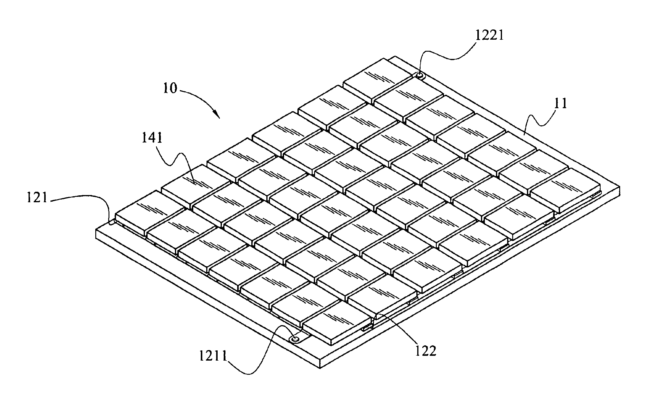
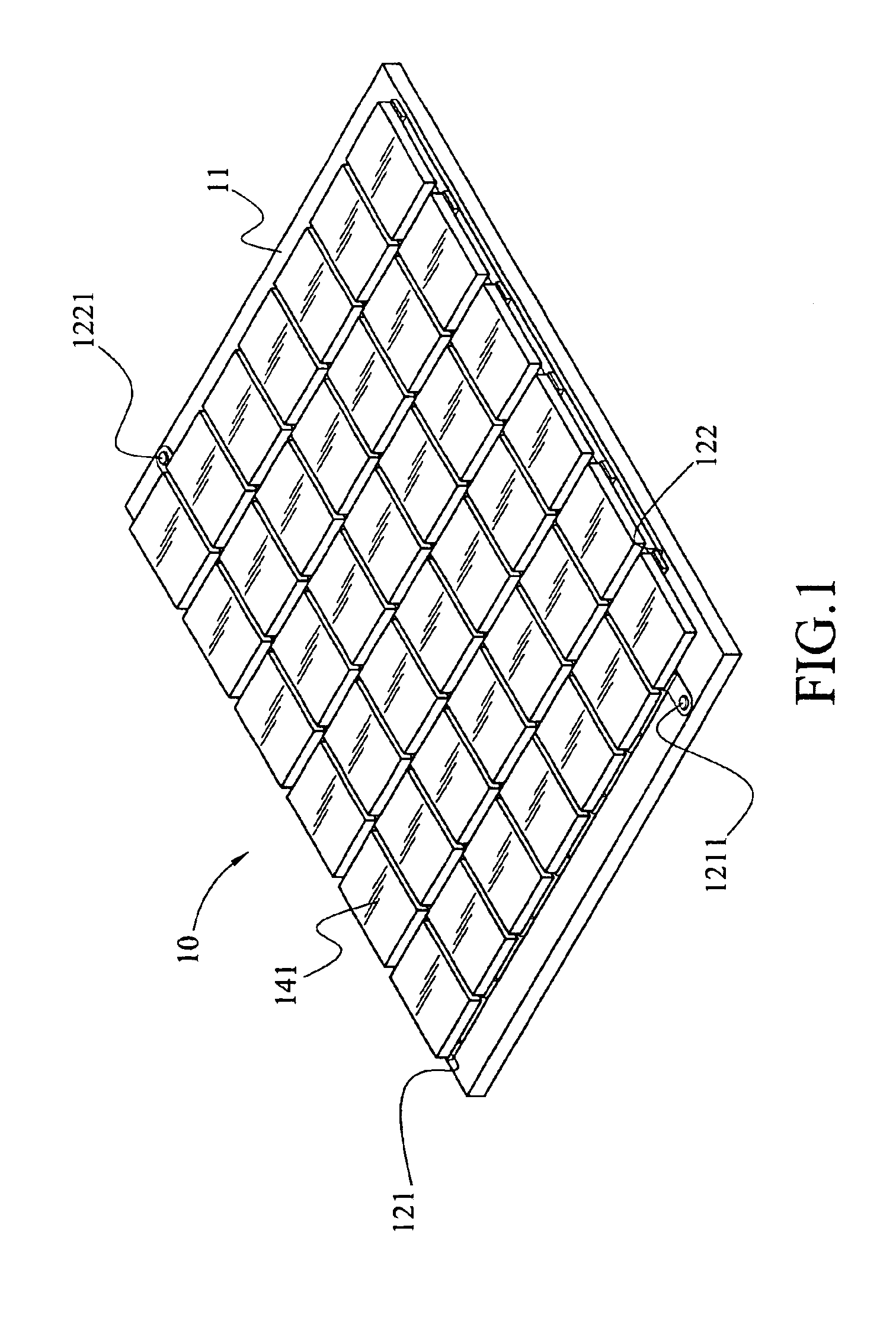
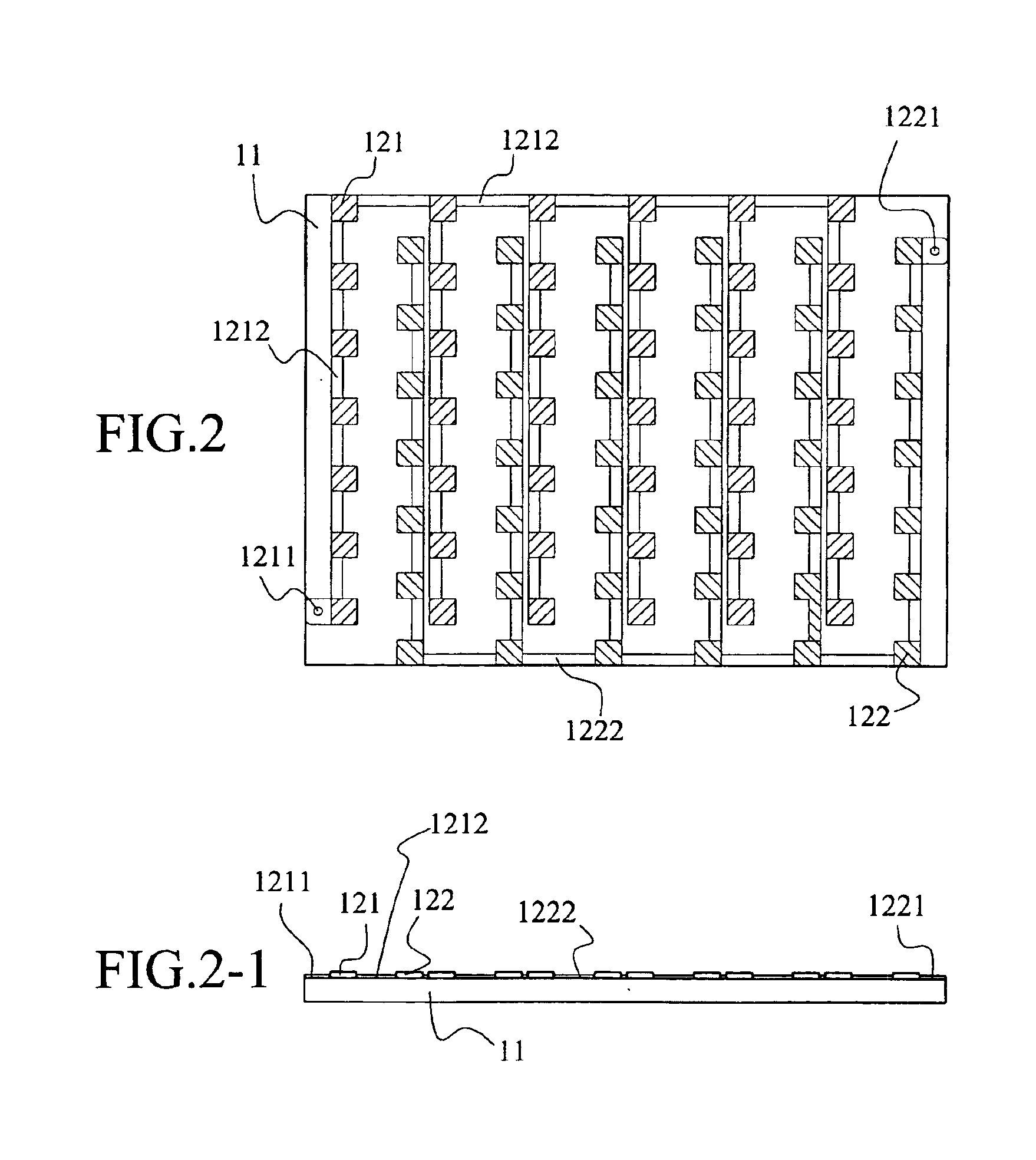
[0027]An LED module 10 may be used in illumination equipment. Referring to FIG. 5, which is the invention, the LED module 10 is mounted in a light bulb 30 as a light source. Two metal wires 20 respectively connect to the p-type electrode junction 1211 and the n-type electrode junction 1221 to complete the electrical connection of the bulb 30. With an electrical current, the bulb 30 illuminates with low power consumption, low pollution and long service life.

second embodiment

[0028]Referring to FIG. 6, which illustrates the invention for dashboard application, a light hybrid layer 40 is applied over the epitaxy chips 141 to emit a specific color of light such as white light. The color light may be obtained by mixing lights of different wavelengths. The light hybrid layer 40 may encapsulate each epitaxy chip 141 so that when the epitaxy chips 141 illuminate, the light coming from the epitaxy chips 141 and transmitting through the light hybrid layer 40 excites the light hybrid layer 40 to create light of a different wavelength. Thereby, a hybrid light is generated via mixing lights of different wavelengths. The light hybrid layer is formed of refracting particles, fluorescent particles or scattering particles. The material for the refracting particles includes quartz, glass or a transparent polymer. The scattering particles are made of a material selected from one or more of titanium barium oxide, titanium oxide, silicon oxide, silicon dioxide, barium sulf...

third embodiment

[0029]FIG. 7 illustrates the invention. A fluorescent layer 50 is applied over the epitaxy chips 141 to encapsulate each epitaxy chip 141. Light from the epitaxy chips 141 emits on the fluorescent layer 50 on the epitaxy chips to excite the fluorescent layer 50 and generate another light of another wavelength. The light emitting from the eptiaxy chips 141 mixes with the light excited from the light hybrid layer 50 to form a different light color. The organic fluorescent material can be varied according to the desired light color. For example, when the fluorescent layer 50 is made of a nitride based material in which yttrium aluminum garnet (YAG) powders are distributed, the mixed light is typically a white light.


PUM


Abstract

A light emitting diode (LED) module illuminates under application of an electrical current for use in an electrical device as a light source. The LED module includes a plurality of epitaxy chips, an electrode set, and a substrate having good electrical insulation and good heat dissipation. The epitaxy chips, formed by cutting an epitaxy wafer, are mounted on the substrate. The LED module has good heat dissipation properties, thereby improving its illumination performance. The electrodes are arranged so that the illuminating area of the LED module is not shielded and can achieve full-area illumination through a large illumination area.

Description

BACKGROUND OF THE INVENTION[0001]1. Field of Invention[0002]The invention relates to a light emitting diode (LED) module as the light source of an electronic device, including an epitaxy chip, an electrode, and a substrate with good insulation and good heat dissipation. More particularly, the invention relates to an LED module having a plurality of epitaxy chips on a single substrate after the epitaxy chips have been cut, the eptiaxy chip having good heat dissipation, high brightness and full-area illumination.[0003]2. Related Art[0004]The development of LED technology began in 1970. For decades, people have looked for an effective means of illumination. However, various factors such as brightness and durability of the illumination products have limited their success in commercialization. With LED technology, some of these problems have been successfully solved, and LEDs are now widely used in illumination devices. Compared to traditional light sources, the LED has advantages such a...

Claims


Application Information

Patent Timeline
Patent Type & Authority Patents(United States)
IPC IPC(8): H05B41/38H05B41/39H05B41/28H05B41/285H05B41/392
CPCH05B33/0803H05B41/2856H05B41/386H05B41/3922H05B45/00
Inventor HO, WEN-CHIH
Owner LEATEC FINE CERAMICS
Why Eureka
Try Eureka