Methods and apparatus for cooling a circuit board component using a heat pipe assembly

Active Publication Date: 2005-07-05
CISCO TECH INC
View PDF23 Cites 78 Cited by
  • Summary
  • Abstract
  • Description
  • Claims
  • Application Information

AI Technical Summary

Benefits of technology

[0009]The present invention is directed to techniques for cooling a circuit board component using a heat pipe having an outer shell that defines an input portion having a first stiffness, and an output portion having a second stiffness, and a compliant portion disposed between the input and output portions having a third stiffness that is less than either the first stiffness or the second stiffness. When the output portion of the heat pipe secures to a support structure (e.g., a metallic tray that operates as an electromagnetic interference shield) coupled to a circuit board, the input portion is capable of reliably contacting a component mounted to the circuit board for adequate heat transfer from the component to the support structure, through the heat pipe. The compliant portion of the heat pipe assembly allows for displacement of the input portion relative to the output portion to limit the amount of stress generated by the heat pipe on the circuit board component. The heat pipe assembly transfers heat from the circuit board component to the support structure, thereby minimizing the need to provide an air stream to remove heat from the circuit board component.
[0010]Embodiments improve upon the heat sinks of the prior art and provide mechanisms for cooling a circuit board component mounted to a circuit board. In one arrangement, a heat pipe assembly provides thermal transfer between a circuit board component, mounted to a circuit board, and a support plane substantially parallel to the circuit board. The circuit board and a first surface of the support plane define a space between the circuit board and support plane with the circuit board component oriented within the space defined by the circuit board and first surface of the support plane. The heat pipe assembly includes an input portion configured to thermally contact the circuit board component, the input portion having a first stiffness and an output portion configured to thermally contact the first surface of the support plane, the output portion having a second stiffness. The heat pipe assembly further includes a transfer portion integrally formed between the input portion and the output portion, the transfer portion having compliant portion having a third stiffness where the third stiffness of the compliant portion is less stiff than the first stiffness of the input portion and is less stiff than the second stiffness of the output portion.

Problems solved by technology

In such an arrangement, the heat pipe and cooling fin combination uses an air stream or airflow to cool the cooling fins, thereby lowering thermal resistance of the cooling fins.
Conventional techniques for utilizing heat pipes to cool circuit board components, such as processors suffer from a variety of deficiencies.
The addition of the heat exchanger to the heat pipe can, however, increase the manufacturing cost of the laptop computer.
Furthermore, in certain cases, the heat exchanger is relatively large and is impractical for use in narrow spaces.
The use of the cooling fins with the heat pipe, however, adds to the manufacturing cost of the workstation.
In the case where the processor is located in a relatively narrow space (e.g., conventional circuit board assembly with approximately 5 mm of space between the circuit board and carrier tray or support plane) use of the relatively

Method used


Image

  • Methods and apparatus for cooling a circuit board component using a heat pipe assembly
  • Methods and apparatus for cooling a circuit board component using a heat pipe assembly
  • Methods and apparatus for cooling a circuit board component using a heat pipe assembly

Examples


Embodiment Construction

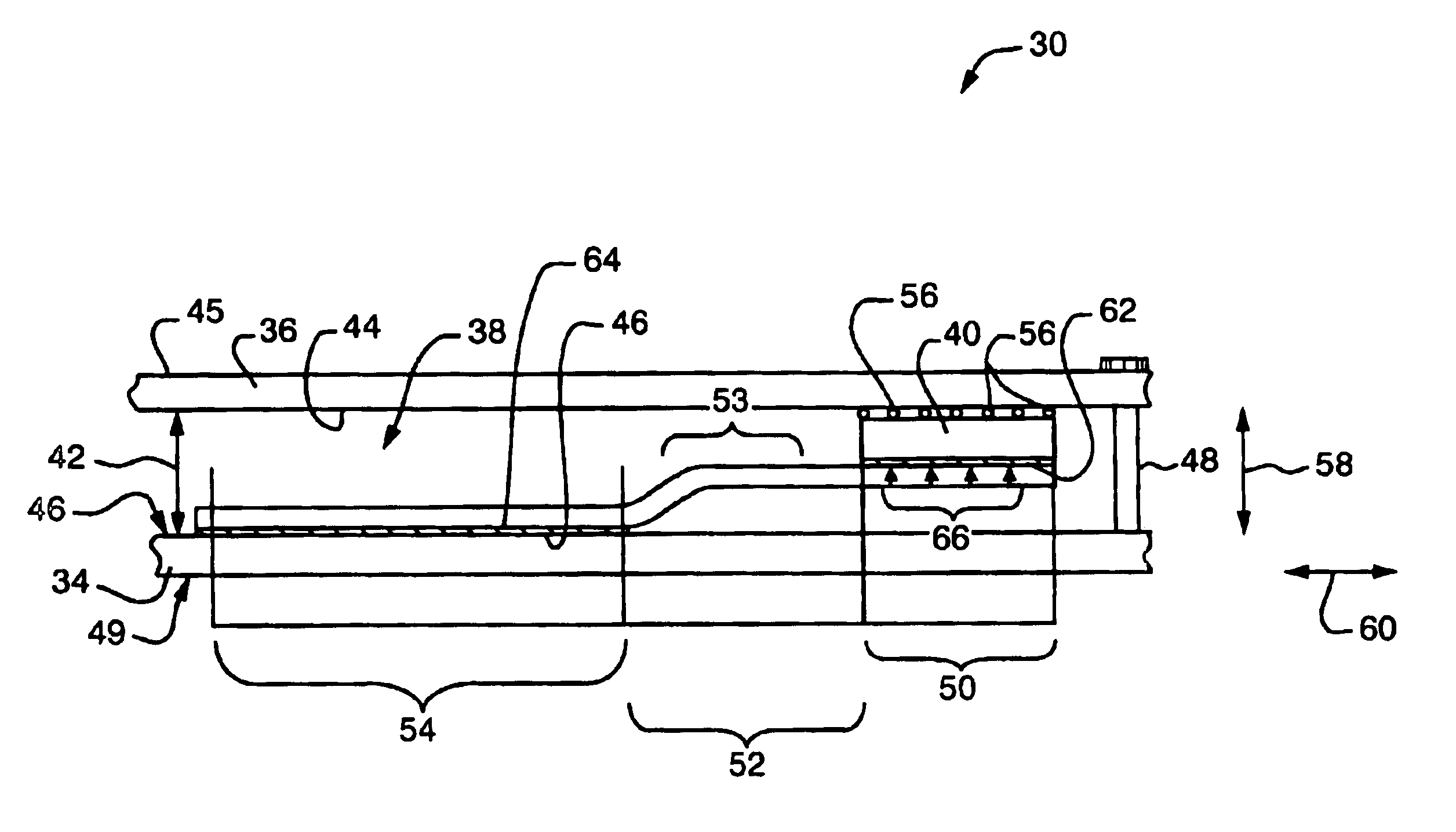
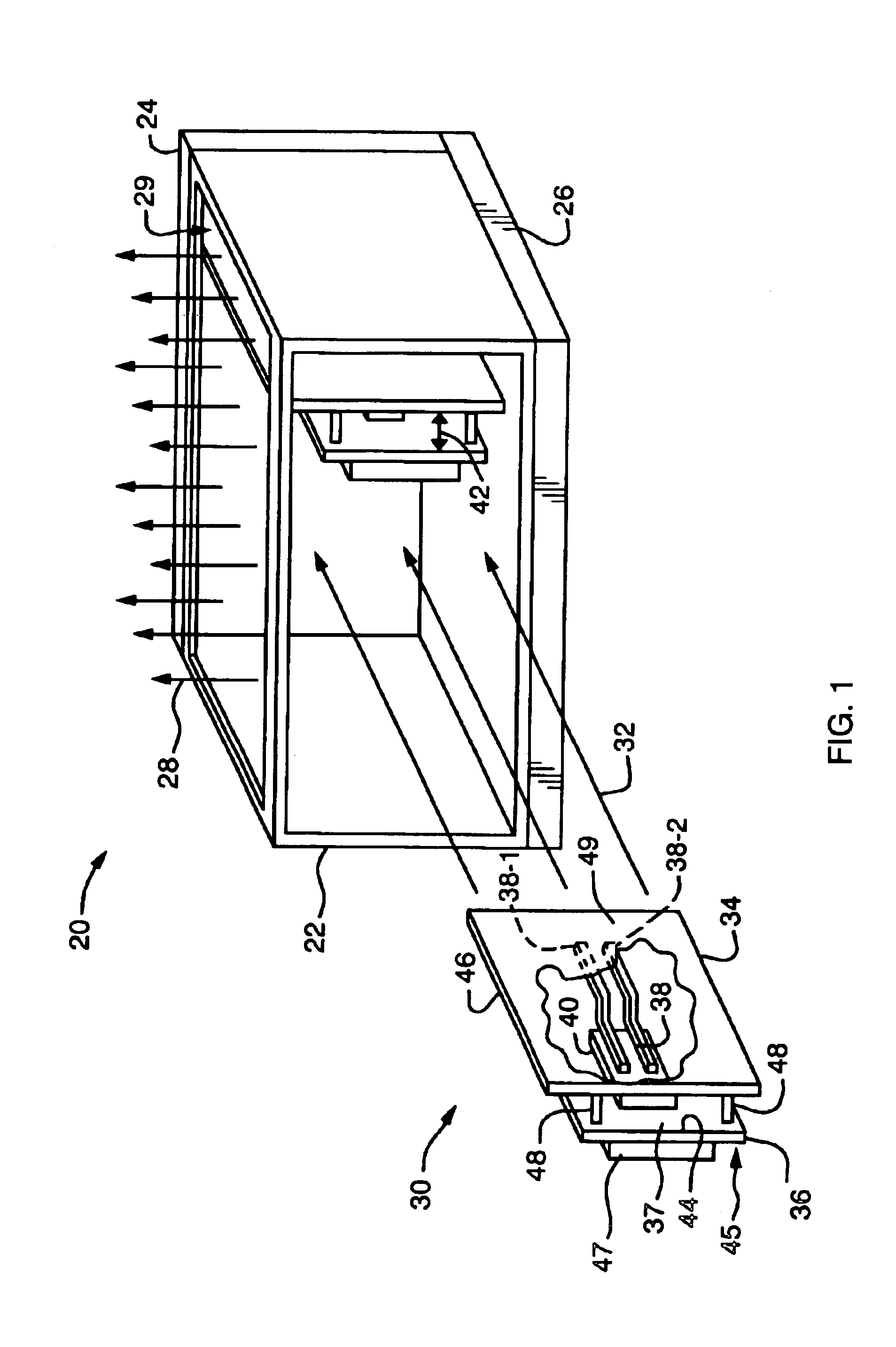
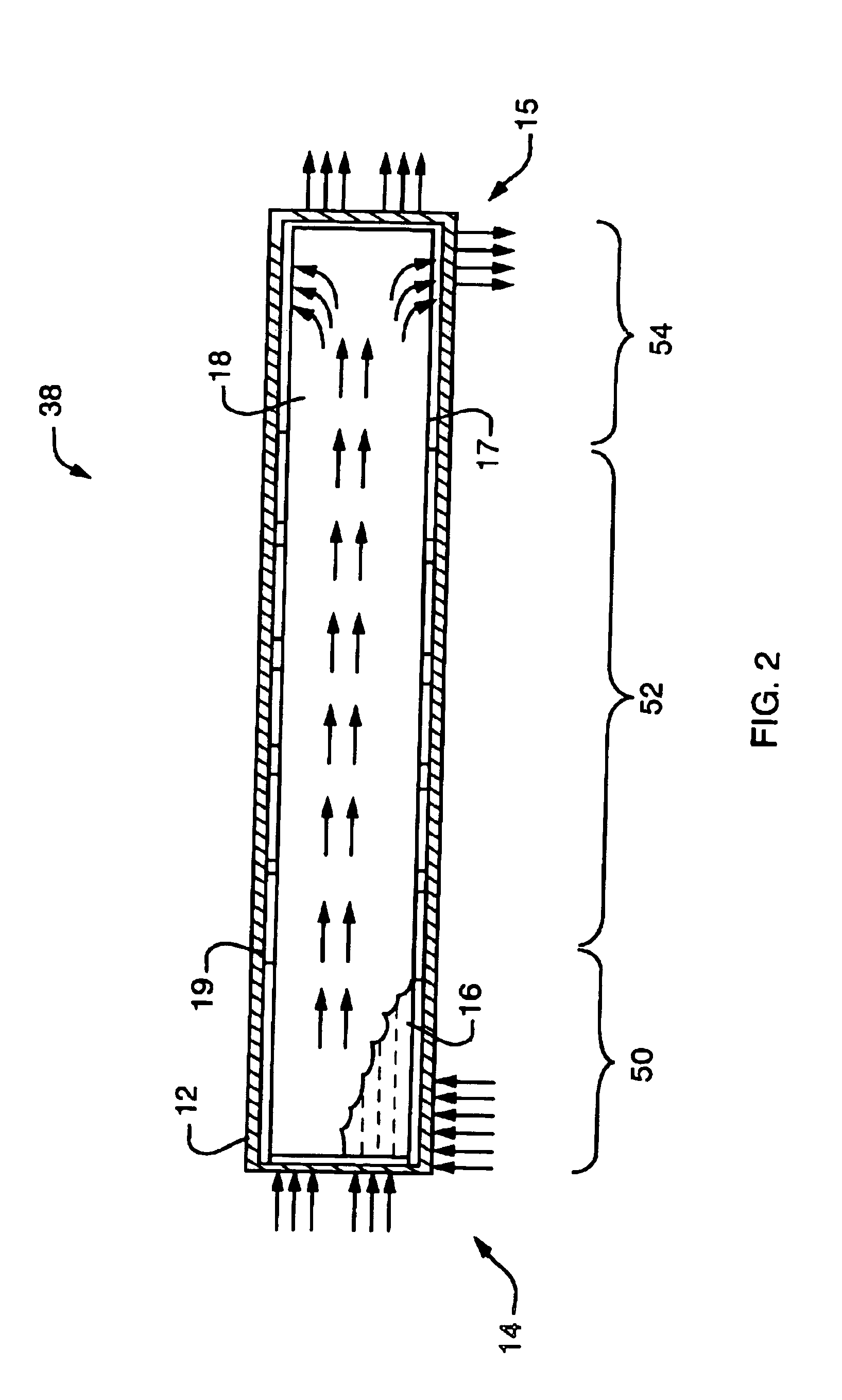
[0027]Embodiments improve upon the heat sinks of the prior art and provide mechanisms for cooling a circuit board component mounted to a circuit board. A circuit board assembly has a circuit board coupled to a support plane and defining a space between the circuit board and the support member. A circuit board component mounts to the circuit board and is oriented within the space defined by the circuit board and the support plane. A heat pipe assembly, located within the defined space, has a relatively high thermal conductivity, compared to other thermally conductive materials, and transfers heat from the circuit board component to the support plane or carrier tray associated with the circuit board. The heat pipe assembly has an input portion that contacts the circuit board component and an output portion that contacts the support plane. The heat pipe assembly also has a compliant portion having a lower stiffness relative to the stiffness of either the input portion or the output por...


PUM


Abstract

A circuit board assembly has a circuit board coupled to a support plane and defining a space between the circuit board and the support member. A circuit board component mounts to the circuit board and is oriented within the space defined by the circuit board and the support plane. A heat pipe assembly, located within the defined space, has a relatively high thermal conductivity, compared to other thermally conductive materials, and transfers heat from the circuit board component to the support plane or carrier tray associated with the circuit board. The heat pipe assembly has an input portion that contacts the circuit board component and an output portion that contacts the support plane. The heat pipe assembly also has a compliant portion having a lower stiffness relative to the stiffness of either the input portion or the output portion. The compliant portion of the heat pipe assembly allows for displacement of the input portion relative to the output portion to limit the amount of stress generated by the heat pipe assembly on the circuit board component.

Description

BACKGROUND OF THE INVENTION[0001]A typical circuit board includes a section of circuit board material (e.g., fiberglass, copper, vias, etc.) and circuit board components attached or mounted to the section of circuit board material. Examples of circuit board components include integrated circuits (ICs) that generate heat during operation. A fan assembly typically generates an air stream that passes over the circuit board components to conduct the heat away from the components. The air stream removes the heat so that the circuit board components do not operate in an unsafe (e.g., relatively high) temperature range that causes the components to perform improperly (e.g., generate a signal incorrectly) or sustain damage (e.g., overheat, burnout, etc.).[0002]Some ICs include heat sinks to facilitate cooling. In general, a heat sink is a flanged metallic device that attaches directly to the package of the IC. As the IC generates heat, heat flows from the IC package to the heat sink, and di...

Claims


Application Information

Patent Timeline
IPC IPC(8): G06F1/20F28D15/02F28D15/04H05K7/20
CPCF28D15/0233F28D15/04G06F1/20
Inventor SHANKER, BANGALORE J.ZOU, YIDACAMERLO, SERGIO
Owner CISCO TECH INC
Why Eureka
Try Eureka